Design Kit Design Your EMC-Filter
Artikel Nr. 744998
Merkmale
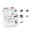
- Dieses Design Kit enthält 10 Testplatinen und eine Auswahl passender Bauteile für den einfachen Aufbau verschiedener Netzfilter.
- Es bietet eine schnelle und kostengünstige Möglichkeit, Netzfilter zur Gleich- und Gegentaktunterdrückung aufzubauen.
- Hierbei handelt es sich um Leiterplatten für Test- und Evaluierungszwecke. Die Platinen sollten nicht in die Endanwendung eingebaut werden.
- Finden Sie den besten Filter für Ihre Anwendung!
Artikeldaten
|
Artikel Nr.
|
Datenblatt
|
Simulation
|
Downloads
|
Status
|
Produktserie
|
IR
(A)
|
L
(mH)
|
RDC max.
(Ω)
|
VR
(V (AC))
|
VT
(V (AC))
|
Muster
|
|---|---|---|---|---|---|---|---|---|---|---|---|
| WE-LF Stromkompensierte Netzdrossel, 0.4 A, 27 mH |
Status
Aktiv
i
| Produktion ist aktiv. Erwartete Lebenszeit: >10 Jahre.
|
Produktserie
WE-LF Stromkompensierte Netzdrossel
|
Nennstrom
0.4 A
|
Induktivität
27 mH
|
Gleichstromwiderstand
1.2 Ω
|
Nennspannung
250 V (AC)
|
Prüfspannung
1500 V (AC)
|
|
|||
| WE-CMB Stromkompensierte Netzdrossel, 0.5 A, 20 mH |
Status
Aktiv
i
| Produktion ist aktiv. Erwartete Lebenszeit: >10 Jahre.
|
Produktserie
WE-CMB Stromkompensierte Netzdrossel
|
Nennstrom
0.5 A
|
Induktivität
20 mH
|
Gleichstromwiderstand
0.54 Ω
|
Nennspannung
250 V (AC)
|
Prüfspannung
1500 V (AC)
|
|
|||
| WE-CMB Stromkompensierte Netzdrossel, 1 A, 10 mH |
Status
Aktiv
i
| Produktion ist aktiv. Erwartete Lebenszeit: >10 Jahre.
|
Produktserie
WE-CMB Stromkompensierte Netzdrossel
|
Nennstrom
1 A
|
Induktivität
10 mH
|
Gleichstromwiderstand
0.36 Ω
|
Nennspannung
250 V (AC)
|
Prüfspannung
1500 V (AC)
|
|
|||
| WE-LF Stromkompensierte Netzdrossel, 1 A, 6.8 mH |
Status
Aktiv
i
| Produktion ist aktiv. Erwartete Lebenszeit: >10 Jahre.
|
Produktserie
WE-LF Stromkompensierte Netzdrossel
|
Nennstrom
1 A
|
Induktivität
6.8 mH
|
Gleichstromwiderstand
0.3 Ω
|
Nennspannung
250 V (AC)
|
Prüfspannung
1500 V (AC)
|
|
|||
| WE-CMB Stromkompensierte Netzdrossel, 1.5 A, 3.3 mH |
Status
Aktiv
i
| Produktion ist aktiv. Erwartete Lebenszeit: >10 Jahre.
|
Produktserie
WE-CMB Stromkompensierte Netzdrossel
|
Nennstrom
1.5 A
|
Induktivität
3.3 mH
|
Gleichstromwiderstand
0.12 Ω
|
Nennspannung
250 V (AC)
|
Prüfspannung
1500 V (AC)
|
|
|||
| WE-CMB Stromkompensierte Netzdrossel, 1.5 A, 20 mH |
Status
Aktiv
i
| Produktion ist aktiv. Erwartete Lebenszeit: >10 Jahre.
|
Produktserie
WE-CMB Stromkompensierte Netzdrossel
|
Nennstrom
1.5 A
|
Induktivität
20 mH
|
Gleichstromwiderstand
0.27 Ω
|
Nennspannung
250 V (AC)
|
Prüfspannung
1500 V (AC)
|
|
|||
| WE-CMB Stromkompensierte Netzdrossel, 2 A, 2.2 mH |
Status
Aktiv
i
| Produktion ist aktiv. Erwartete Lebenszeit: >10 Jahre.
|
Produktserie
WE-CMB Stromkompensierte Netzdrossel
|
Nennstrom
2 A
|
Induktivität
2.2 mH
|
Gleichstromwiderstand
0.07 Ω
|
Nennspannung
250 V (AC)
|
Prüfspannung
1500 V (AC)
|
|
|||
| WE-CMB Stromkompensierte Netzdrossel, 2 A, 10 mH |
Status
Aktiv
i
| Produktion ist aktiv. Erwartete Lebenszeit: >10 Jahre.
|
Produktserie
WE-CMB Stromkompensierte Netzdrossel
|
Nennstrom
2 A
|
Induktivität
10 mH
|
Gleichstromwiderstand
0.125 Ω
|
Nennspannung
250 V (AC)
|
Prüfspannung
1500 V (AC)
|
|
|||
| WE-CMB Stromkompensierte Netzdrossel, 2 A, 20 mH |
Status
Aktiv
i
| Produktion ist aktiv. Erwartete Lebenszeit: >10 Jahre.
|
Produktserie
WE-CMB Stromkompensierte Netzdrossel
|
Nennstrom
2 A
|
Induktivität
20 mH
|
Gleichstromwiderstand
0.22 Ω
|
Nennspannung
250 V (AC)
|
Prüfspannung
1500 V (AC)
|
|
|||
| WE-LF Stromkompensierte Netzdrossel, 2 A, 2.2 mH |
Status
Aktiv
i
| Produktion ist aktiv. Erwartete Lebenszeit: >10 Jahre.
|
Produktserie
WE-LF Stromkompensierte Netzdrossel
|
Nennstrom
2 A
|
Induktivität
2.2 mH
|
Gleichstromwiderstand
0.1 Ω
|
Nennspannung
250 V (AC)
|
Prüfspannung
1500 V (AC)
|
|
|||
| WE-CMB Stromkompensierte Netzdrossel, 2.5 A, 5 mH |
Status
Aktiv
i
| Produktion ist aktiv. Erwartete Lebenszeit: >10 Jahre.
|
Produktserie
WE-CMB Stromkompensierte Netzdrossel
|
Nennstrom
2.5 A
|
Induktivität
5 mH
|
Gleichstromwiderstand
0.095 Ω
|
Nennspannung
250 V (AC)
|
Prüfspannung
1500 V (AC)
|
|
|||
| WE-CMB Stromkompensierte Netzdrossel, 3 A, 1 mH |
Status
Aktiv
i
| Produktion ist aktiv. Erwartete Lebenszeit: >10 Jahre.
|
Produktserie
WE-CMB Stromkompensierte Netzdrossel
|
Nennstrom
3 A
|
Induktivität
1 mH
|
Gleichstromwiderstand
0.035 Ω
|
Nennspannung
250 V (AC)
|
Prüfspannung
1500 V (AC)
|
|
|||
| WE-CMB Stromkompensierte Netzdrossel, 3 A, 10 mH |
Status
Aktiv
i
| Produktion ist aktiv. Erwartete Lebenszeit: >10 Jahre.
|
Produktserie
WE-CMB Stromkompensierte Netzdrossel
|
Nennstrom
3 A
|
Induktivität
10 mH
|
Gleichstromwiderstand
0.105 Ω
|
Nennspannung
250 V (AC)
|
Prüfspannung
1500 V (AC)
|
|
|||
| WE-CMB Stromkompensierte Netzdrossel, 4 A, 2.2 mH |
Status
Aktiv
i
| Produktion ist aktiv. Erwartete Lebenszeit: >10 Jahre.
|
Produktserie
WE-CMB Stromkompensierte Netzdrossel
|
Nennstrom
4 A
|
Induktivität
2.2 mH
|
Gleichstromwiderstand
0.03 Ω
|
Nennspannung
250 V (AC)
|
Prüfspannung
1500 V (AC)
|
|
|||
| WE-CMB Stromkompensierte Netzdrossel, 4 A, 3.3 mH |
Status
Aktiv
i
| Produktion ist aktiv. Erwartete Lebenszeit: >10 Jahre.
|
Produktserie
WE-CMB Stromkompensierte Netzdrossel
|
Nennstrom
4 A
|
Induktivität
3.3 mH
|
Gleichstromwiderstand
0.035 Ω
|
Nennspannung
250 V (AC)
|
Prüfspannung
1500 V (AC)
|
|
|||
| WE-LF Stromkompensierte Netzdrossel, 4 A, 0.7 mH |
Status
Aktiv
i
| Produktion ist aktiv. Erwartete Lebenszeit: >10 Jahre.
|
Produktserie
WE-LF Stromkompensierte Netzdrossel
|
Nennstrom
4 A
|
Induktivität
0.7 mH
|
Gleichstromwiderstand
0.027 Ω
|
Nennspannung
250 V (AC)
|
Prüfspannung
1500 V (AC)
|
|
|||
| WE-CMBNC Stromkompensierte Netzdrossel Nanokristallin, 5 A, 9 mH |
Status
Aktiv
i
| Produktion ist aktiv. Erwartete Lebenszeit: >10 Jahre.
|
Nennstrom
5 A
|
Induktivität
9 mH
|
Gleichstromwiderstand
0.032 Ω
|
Nennspannung
300 V (AC)
|
Prüfspannung
2100 V (AC)
|
|
||||
| WE-CMB Stromkompensierte Netzdrossel, 6 A, 1 mH |
Status
Aktiv
i
| Produktion ist aktiv. Erwartete Lebenszeit: >10 Jahre.
|
Produktserie
WE-CMB Stromkompensierte Netzdrossel
|
Nennstrom
6 A
|
Induktivität
1 mH
|
Gleichstromwiderstand
0.013 Ω
|
Nennspannung
250 V (AC)
|
Prüfspannung
1500 V (AC)
|
|
|||
| WE-CMB Stromkompensierte Netzdrossel, 6 A, 2.2 mH |
Status
Aktiv
i
| Produktion ist aktiv. Erwartete Lebenszeit: >10 Jahre.
|
Produktserie
WE-CMB Stromkompensierte Netzdrossel
|
Nennstrom
6 A
|
Induktivität
2.2 mH
|
Gleichstromwiderstand
0.02 Ω
|
Nennspannung
250 V (AC)
|
Prüfspannung
1500 V (AC)
|
|
|||
| WE-CMBNC Stromkompensierte Netzdrossel Nanokristallin, 7 A, 7 mH |
Status
Aktiv
i
| Produktion ist aktiv. Erwartete Lebenszeit: >10 Jahre.
|
Nennstrom
7 A
|
Induktivität
7 mH
|
Gleichstromwiderstand
0.022 Ω
|
Nennspannung
300 V (AC)
|
Prüfspannung
2100 V (AC)
|
|
||||
| WE-CMB Stromkompensierte Netzdrossel, 7.5 A, 1 mH |
Status
Aktiv
i
| Produktion ist aktiv. Erwartete Lebenszeit: >10 Jahre.
|
Produktserie
WE-CMB Stromkompensierte Netzdrossel
|
Nennstrom
7.5 A
|
Induktivität
1 mH
|
Gleichstromwiderstand
0.01 Ω
|
Nennspannung
250 V (AC)
|
Prüfspannung
1500 V (AC)
|
|
|||
| WP-SMSH REDCUBE SMT with external thread with Pin, 50 A, – |
Simulation
–
|
Status
Aktiv
i
| Produktion ist aktiv. Erwartete Lebenszeit: >10 Jahre.
|
Produktserie
WP-SMSH REDCUBE SMT with external thread with Pin
|
Nennstrom
50 A
|
–
|
–
|
–
|
–
|
|
||
| WP-SMSH REDCUBE SMT with external thread with Pin, 50 A, – |
Simulation
–
|
Status
Aktiv
i
| Produktion ist aktiv. Erwartete Lebenszeit: >10 Jahre.
|
Produktserie
WP-SMSH REDCUBE SMT with external thread with Pin
|
Nennstrom
50 A
|
–
|
–
|
–
|
–
|
|
||
| WCAP-FTX2 Folienkondensatoren, –, – |
Status
Aktiv
i
| Produktion ist aktiv. Erwartete Lebenszeit: >10 Jahre.
|
Produktserie
WCAP-FTX2 Folienkondensatoren
|
–
|
–
|
–
|
Nennspannung
275 V (AC)
|
–
|
|
|||
| WCAP-FTX2 Folienkondensatoren, –, – |
Status
Aktiv
i
| Produktion ist aktiv. Erwartete Lebenszeit: >10 Jahre.
|
Produktserie
WCAP-FTX2 Folienkondensatoren
|
–
|
–
|
–
|
Nennspannung
275 V (AC)
|
–
|
|
|||
| WCAP-FTX2 Folienkondensatoren, –, – |
Status
Aktiv
i
| Produktion ist aktiv. Erwartete Lebenszeit: >10 Jahre.
|
Produktserie
WCAP-FTX2 Folienkondensatoren
|
–
|
–
|
–
|
Nennspannung
275 V (AC)
|
–
|
|
|||
| WA-SNSR Self-Retaining Spacer, –, – |
Simulation
–
|
Status
Aktiv
i
| Produktion ist aktiv. Erwartete Lebenszeit: >10 Jahre.
|
Produktserie
WA-SNSR Self-Retaining Spacer
|
–
|
–
|
–
|
–
|
–
|
|
||
| WCAP-CSSA Interference Suppression, –, – |
Status
Aktiv
i
| Produktion ist aktiv. Erwartete Lebenszeit: >10 Jahre.
|
Produktserie
WCAP-CSSA Interference Suppression
|
–
|
–
|
–
|
Nennspannung
250 V (AC)
|
–
|
|
|||
| WCAP-CSSA Interference Suppression, –, – |
Status
Aktiv
i
| Produktion ist aktiv. Erwartete Lebenszeit: >10 Jahre.
|
Produktserie
WCAP-CSSA Interference Suppression
|
–
|
–
|
–
|
Nennspannung
250 V (AC)
|
–
|
|
|||
| WCAP-CSSA Interference Suppression, –, – |
Status
Aktiv
i
| Produktion ist aktiv. Erwartete Lebenszeit: >10 Jahre.
|
Produktserie
WCAP-CSSA Interference Suppression
|
–
|
–
|
–
|
Nennspannung
250 V (AC)
|
–
|
|
|||
| WCAP-CSSA Interference Suppression, –, – |
Status
Aktiv
i
| Produktion ist aktiv. Erwartete Lebenszeit: >10 Jahre.
|
Produktserie
WCAP-CSSA Interference Suppression
|
–
|
–
|
–
|
Nennspannung
250 V (AC)
|
–
|
|
Filterlösungen schnell und kostengünstig finden mit dem
Design Your EMC-Filter Design Kit
Filterlösungen schnell und kostengünstig finden mit dem
Design Your EMC-Filter Design Kit
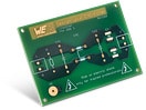
Dieses Design Kit bietet eine schnelle und kostengünstige Möglichkeit, das Filterdesign mit verschiedenen Komponenten aufzubauen. Es ermöglicht die Überprüfung des Verhaltens der Filterschaltung hinsichtlich der gewünschten Filterwirkung und die Integration der ausgewählten Filterschaltung in die Anwendung. Auf diese Weise können Entwicklungszeiten und damit verbundene Kosten minimiert werden.
Für noch mehr Möglichkeiten im Filterdesign, schauen Sie auch unsere Evaluation Boards für spezifische Anwendungen an.

Aufbau und Funktionsweise
Aufbau und Funktionsweise
Der Entladewiderstand (R) ermöglicht eine Entladung des X-Kondensators (Cx) ohne Last.
Der X-Kondensator (Cx) stellt für Gegentaktstörungen bei hohen Frequenzen eine niedrige Impedanz dar.
Die stromkompensierte Drossel (CMC) bringt die nötige Induktivität für Gegentakt- und Gleichtaktstörungen. Somit stellt diese Drossel bei hohen Frequenzen im Vergleich zu den Kondensatoren eine größere Impedanz dar.
Die Y-Kondensatoren (CY1, CY2) ermöglichen eine Ableitung von hochfrequenten Gleichtaktstörströmen zur geräteinternen Erde.

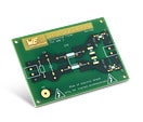
Tiefpassfilter zur Gleich- und Gegentaktunterdrückung

Gleichtaktfilter
Bei Gleichtaktstörungen ist die Induktivität der stromkompensierten Drossel (CMC) relativ hoch. Mit dieser Induktivität und den Y-Kondensatoren (CY1, CY2) bildet sich für höherfrequente Gleichtaktstörströme ein Tiefpassfilter. Dabei eröffnen die Y-Kondensatoren von jedem Leiter aus einen Strompfad zur internen Erde, wodurch hochfrequente Gleichtaktstörströme abgeleitet werden. Durch die hohe Impedanz, welche die stromkompensierte Drossel für die hochfrequenten Gleichtaktstörströme bereitstellt, werden diese abgeschwächt.

Gegentaktfilter
Bei Gegentaktstörungen fließt der Strom durch den Hinleiter L und über den Neutralleiter N zurück. Vereinfacht dargestellt, bilden die Streuinduktivität (LLeak) der stromkompensierten Drossel, welche bei Gegentakt herrscht, und der X-Kondensator (Cx) einen Tiefpassfilter. Durch diesen Tiefpassfilter schließt sich die Masche des versorgungsseitig eingespeisten, höherfrequenten Störstroms über den Rückleiter im Netz selbst. Während der Versorgungsstrom, welcher im Vergleich zum Störstom niederfrequenter ist (50 Hz), den Filter wie gewünscht passiert.
Einfügedämpfung Beispielaufbauten

Beispiel 1 gemessen mit:
CMC: WE-CMB S / 744 822 110 /
L = 10 mH / IR = 1 A
Cx: 890 324 023 025 /
C = 0,15 µF / UR = 275 VAC
Cy: 885 352 213 015 1/
C = 2200 pF / UR = 250 VAC

Beispiel 2 gemessen mit:
CMC: WE-CMB L / 744 824 220 /
L = 20 mH / IR = 2 A
Cx: 890 324 023 025 /
C = 0,15 µF / UR = 275 VAC
Cy: 885 352 213 015 1/
C = 2200 pF / UR = 250 VAC

Beispiel 3 gemessen mit:
CMC: WE-LF / 744 662 200 2 /
L = 2,2 mH / IR = 2 A
Cx: 890 324 023 025 /
C = 0,15 µF / UR = 275 VAC
Cy: 885 352 213 015 1/
C = 2200 pF / UR = 250 VAC

Beispiel 4 gemessen mit:
CMC: WE-CMBNC M / 744 803 050 9 /
L = 9 mH / IR = 5 A
Cx: 890 324 023 025 /
C = 0,15 µF / UR = 275 VAC
Cy: 885 352 213 015 1/
C = 2200 pF / UR = 250 VAC
Evaluation Boards
Auch interessant
Videos
#askLorandt erklärt: Schritt für Schritt-Aufbau eines EMV-Netzfilters
Videos
#askLorandt erklärt: EMV-Filter Design Kit
Videos
Würth Elektronik Webinar: Wie löse ich EMV-Probleme auf Platinenebene?