Overview
| Topology | Battery Management System |
| IC revision | 2.0 |
Description
The AEK-POW-BMSCC is a very compact battery management system (BMS) evaluation board.It can be used in a centralized daisy chain as an intermediate node, where the first node is an AEK-POW-BMSCCTX. As an intermediate node, the AEK-POW-BMSCC can be part of a chain of up to 31 BMS nodes.Each battery node manages from 4 to 14 battery cells. The total voltage of the chain may range from 48 to 800 V.The ability to easily integrate into a system, compact dimensions, and a wide range of applications make this compact BMS system ideal for any solution enhancing battery life, efficiency, and cost effectiveness during use and operation.The small size allows for greater flexibility in battery pack installation, addressing the challenges of using a BMS in confined spaces.Its compact design allows it to fit easily, enabling more batteries to be installed within the same volume. This increases the overall battery storage, providing robust performance without adding unnecessary weight. It emphasizes the growing trend of making energy solutions more accessible and effective across different applications.The main activity of the L9963E is monitoring cells and battery node status through stack voltage measurement, cell voltage measurement, temperature measurement, and coulomb counting.Measurement and diagnostic tasks can be executed either on demand or periodically, with a programmable cycle interval.Measurement data are available for an external microcontroller to perform charge balancing and to compute the state of charge (SoC) and the state of health (SOH).The main functions of a standard BMS are monitoring and protecting the battery pack.The monitoring function is related to the measurement of the battery current, voltage, and temperature. The protection function brings the system to a safety state in case of under or overvoltage and overheating.The AEK-POW-BMSCC provides an elaborate monitoring network to sense the voltage, current, and temperature of each cell.This sensing allows elaborating the SoC of each battery cell and, consequently, the state of charge of all battery packs. The SoC allows assessing the remaining battery capacity.For maintenance reasons, it is important to monitor the SoC estimation over time. According to our algorithm for the SoC calculation, the more the SoC differs from its nominal value (that is, its value when the batteries are new), the more a cell of the battery pack risks overdischarging.The SoC evolution overtime allows asserting the state of health (SOH) of a cell or a battery pack to spot early indications that a cell is at risk of overdischarge or overcharging.The SoC of a battery cell is required to maintain its safe operation and duration during charge, discharge, and storage.The SoC cannot be measured directly and is estimated from other measurements and known parameters (such as characterization curves or look-up tables). This information on the battery cells is necessary to determine how the voltage varies according to the current, the temperature, etc., on the basis of the battery chemical composition and production lot used.The AEK-POW-BMSCC can work in a daisy chain-centralized configuration.In this configuration, a series of BMS is connected to an MCU board through an AEK-POW-BMSCCTX, used as the first node in the chain.The ISOH connectors present on the AEK-POW-BMSCCTX board allow the BMS to be connected to each other via ISO SPI communication. The board is then connected to the AEK-POW-BMSCC through the ISOL connector.The MCU communicates with the L9963T transceiver hosted on the AEK-POW-BMSCCTX through the SPI protocol. The transceiver converts these signals into ISO SPI signals to communicate with the next BMS of the chain.In the AutoDevKit ecosystem software package, we created an example demo for centralized configuration to elaborate SoC and SOH, using Li-ion batteries.Battery packs may have different SOCs, and balancing is necessary to bring them all to the same charge level. After detecting the lowest charge in the battery pack, all the other battery nodes are discharged to reach its level.The demo explains how to activate the internal MOSFETs of the L9963E, which short-circuit the cell on an external dissipation resistor to discharge it.These L9963E internal MOSFETs perform passive cell balancing. The controller can either manually control the balancing drivers or start a balancing task with a fixed duration.In the second case, called silent mode, the balancing may be programmed to continue even when the IC enters a low-power mode, to avoid unnecessary current absorption from the battery pack.The balancing function is necessary to lengthen the battery capacity and its duration.Different MCUs can be used. In our demo, we used the AEK-MCU-C4MINI1, while other ASIL-B and ASIL-D microcontrollers of the SPC58 chorus family are supported.State of charge, voltage, current, balancing status of selected chains and nodes can be monitored through a dedicated GUI.
Features
Hosts the L9963E AEC-Q100 qualified automotive multicell battery monitoring and balancing ICISOSPI interfaces to communicate with the other chain nodesVoltage monitoring of up to 14 battery cellsCurrent sensing of the entire battery pack5 configurable GPIOs, pluggable with NTCs for temperature measurementAn NTC hosted on the L9963E to sense the chip temperaturePassive cell balancingTwo connectors for easy and fast plug-and-playPackaged in a very compact size: 70 x 45 mmIncluded in the AutoDevKit ecosystem
Typical applications
- Electro-mobility
More information
Products
| Order Code | Datasheet | Simulation | Downloads | Status | Product series | λDom typ. (nm) | Emitting Color | λPeak typ. (nm) | IV typ. (mcd) | VF typ. (V) | Chip Technology | 2θ50% typ. (°) | Gender | Pins | Type | Wire Section | Contact Plating | IR (A) | Working Voltage (V (AC)) | Contact Resistance (mΩ) | Packaging | Qty. (pcs) | Stranded Wire Section (AWG) | Stranded Wire Section (Metric) | C | Tol. C | VR (V (DC)) | Size | Operating Temperature | Q (%) | DF (%) | RISO | Ceramic Type | L (mm) | W (mm) | H (mm) | Fl (mm) | R | Tol. R | PRated (W) | TCR (ppm/ °C) | TCR (ppm/ °C) | VE (V) | Mount | IR (A) | PCB/Cable/Panel | Samples | |
|---|---|---|---|---|---|---|---|---|---|---|---|---|---|---|---|---|---|---|---|---|---|---|---|---|---|---|---|---|---|---|---|---|---|---|---|---|---|---|---|---|---|---|---|---|---|---|---|---|
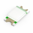
 | 150120GS75000 | SPEC | 7 files | Active i| Production is active. Expected lifetime: >10 years. | WL-SMCW SMT Mono-color Chip LED Waterclear | 525 | Green | 515 | 450 | 3.2 | InGaN | 140 | – | – | – | – | – | – | – | – | Tape and Reel | 4000 | – | – | – | – | – | 1206 | -40 °C up to +85 °C | – | – | – | – | 3.2 | 1.6 | 0.68 | – | – | – | – | – | – | – | SMT | – | – | ||
| 885012006053 | SPEC | 9 files | Active i| Production is active. Expected lifetime: >10 years. | WCAP-CSGP MLCCs 50 V(DC) | – | – | – | – | – | – | – | – | – | – | – | – | – | – | – | 7" Tape & Reel | 4000 | – | – | 22 pF | ±5% | 50 | 0603 | -55 °C up to +125 °C | 840 | – | 10 GΩ | NP0 Class I | 1.6 | 0.8 | 0.8 | 0.4 | – | – | – | – | – | – | – | – | – | |||
| 885012006054 | SPEC | 9 files | Active i| Production is active. Expected lifetime: >10 years. | WCAP-CSGP MLCCs 50 V(DC) | – | – | – | – | – | – | – | – | – | – | – | – | – | – | – | 7" Tape & Reel | 4000 | – | – | 33 pF | ±5% | 50 | 0603 | -55 °C up to +125 °C | 1000 | – | 10 GΩ | NP0 Class I | 1.6 | 0.8 | 0.8 | 0.4 | – | – | – | – | – | – | – | – | – | |||
| 885012206085 | SPEC | 9 files | Active i| Production is active. Expected lifetime: >10 years. | WCAP-CSGP MLCCs 50 V(DC) | – | – | – | – | – | – | – | – | – | – | – | – | – | – | – | 7" Tape & Reel | 4000 | – | – | 2.2 nF | ±10% | 50 | 0603 | -55 °C up to +125 °C | – | 2.5 | 10 GΩ | X7R Class II | 1.6 | 0.8 | 0.8 | 0.4 | – | – | – | – | – | – | – | – | – | |||
| 885012206087 | SPEC | 9 files | Active i| Production is active. Expected lifetime: >10 years. | WCAP-CSGP MLCCs 50 V(DC) | – | – | – | – | – | – | – | – | – | – | – | – | – | – | – | 7" Tape & Reel | 4000 | – | – | 4.7 nF | ±10% | 50 | 0603 | -55 °C up to +125 °C | – | 2.5 | 10 GΩ | X7R Class II | 1.6 | 0.8 | 0.8 | 0.4 | – | – | – | – | – | – | – | – | – | |||
| 885012206088 | SPEC | 9 files | Active i| Production is active. Expected lifetime: >10 years. | WCAP-CSGP MLCCs 50 V(DC) | – | – | – | – | – | – | – | – | – | – | – | – | – | – | – | 7" Tape & Reel | 4000 | – | – | 6.8 nF | ±10% | 50 | 0603 | -55 °C up to +125 °C | – | 2.5 | 10 GΩ | X7R Class II | 1.6 | 0.8 | 0.8 | 0.4 | – | – | – | – | – | – | – | – | – | |||
| 885012206089 | SPEC | 9 files | Active i| Production is active. Expected lifetime: >10 years. | WCAP-CSGP MLCCs 50 V(DC) | – | – | – | – | – | – | – | – | – | – | – | – | – | – | – | 7" Tape & Reel | 4000 | – | – | 10 nF | ±10% | 50 | 0603 | -55 °C up to +125 °C | – | 2.5 | 10 GΩ | X7R Class II | 1.6 | 0.8 | 0.8 | 0.4 | – | – | – | – | – | – | – | – | – | |||
| 885012206093 | SPEC | 9 files | Active i| Production is active. Expected lifetime: >10 years. | WCAP-CSGP MLCCs 50 V(DC) | – | – | – | – | – | – | – | – | – | – | – | – | – | – | – | 7" Tape & Reel | 4000 | – | – | 47 nF | ±10% | 50 | 0603 | -55 °C up to +125 °C | – | 3 | 10 GΩ | X7R Class II | 1.6 | 0.8 | 0.8 | 0.4 | – | – | – | – | – | – | – | – | – | |||
| 885012206094 | SPEC | 9 files | Active i| Production is active. Expected lifetime: >10 years. | WCAP-CSGP MLCCs 50 V(DC) | – | – | – | – | – | – | – | – | – | – | – | – | – | – | – | 7" Tape & Reel | 4000 | – | – | 68 nF | ±10% | 50 | 0603 | -55 °C up to +125 °C | – | 3 | 7.4 GΩ | X7R Class II | 1.6 | 0.8 | 0.8 | 0.4 | – | – | – | – | – | – | – | – | – | |||
| 885012207079 | SPEC | 8 files | Active i| Production is active. Expected lifetime: >10 years. | WCAP-CSGP MLCCs 25 V(DC) | – | – | – | – | – | – | – | – | – | – | – | – | – | – | – | 7" Tape & Reel | 3000 | – | – | 2.2 µF | ±10% | 25 | 0805 | -55 °C up to +125 °C | – | 10 | 0.05 GΩ | X7R Class II | 2 | 1.25 | 1.25 | 0.5 | – | – | – | – | – | – | – | – | – | |||
| 885012207103 | SPEC | 9 files | Active i| Production is active. Expected lifetime: >10 years. | WCAP-CSGP MLCCs 50 V(DC) | – | – | – | – | – | – | – | – | – | – | – | – | – | – | – | 7" Tape & Reel | 3000 | – | – | 1 µF | ±10% | 50 | 0805 | -55 °C up to +125 °C | – | 10 | 0.1 GΩ | X7R Class II | 2 | 1.25 | 1.25 | 0.5 | – | – | – | – | – | – | – | – | – | |||
| 885012208094 | SPEC | 9 files | Active i| Production is active. Expected lifetime: >10 years. | WCAP-CSGP MLCCs 50 V(DC) | – | – | – | – | – | – | – | – | – | – | – | – | – | – | – | 7" Tape & Reel | 2000 | – | – | 4.7 µF | ±10% | 50 | 1206 | -55 °C up to +125 °C | – | 10 | 0.02 GΩ | X7R Class II | 3.2 | 1.6 | 1.6 | 0.5 | – | – | – | – | – | – | – | – | – | |||
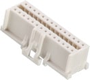
 | 624028213322 | SPEC | – | 3 files | Active i| Production is active. Expected lifetime: >10 years. | WR-WTB 2.00 mm Female Dual Row Terminal Housing w. positive locking | – | – | – | – | – | – | – | Female | 28 | Terminal Housing | – | – | – | – | – | Bag | – | – | – | – | – | – | – | -25 °C up to +85 °C | – | – | 1000 MΩ | – | 31.4 | – | – | – | – | – | – | – | – | – | – | – | Cable | |
 | 624030213322 | SPEC | – | 3 files | Active i| Production is active. Expected lifetime: >10 years. | WR-WTB 2.00 mm Female Dual Row Terminal Housing w. positive locking | – | – | – | – | – | – | – | Female | 30 | Terminal Housing | – | – | – | – | – | Bag | – | – | – | – | – | – | – | -25 °C up to +85 °C | – | – | 1000 MΩ | – | 33.4 | – | – | – | – | – | – | – | – | – | – | – | Cable | |
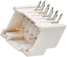
 | 62402821722 | SPEC | – | 7 files | Active i| Production is active. Expected lifetime: >10 years. | WR-WTB 2.00 mm Male Header | – | – | – | – | – | – | – | Male | 28 | Horizontal | – | Tin | 3 | 250 | 20 | Tube | – | – | – | – | – | – | – | -25 °C up to +85 °C | – | – | 1000 MΩ | – | 31.4 | – | – | – | – | – | – | – | – | – | THT | 3 | PCB | |
 | 62403021722 | SPEC | – | 7 files | Active i| Production is active. Expected lifetime: >10 years. | WR-WTB 2.00 mm Male Header | – | – | – | – | – | – | – | Male | 30 | Horizontal | – | Tin | 3 | 250 | 20 | Tube | – | – | – | – | – | – | – | -25 °C up to +85 °C | – | – | 1000 MΩ | – | 33.4 | – | – | – | – | – | – | – | – | – | THT | 3 | PCB | |
 | 62400113722 | SPEC | – | 3 files | Active i| Production is active. Expected lifetime: >10 years. | WR-WTB 2.00 mm Female Dual Row Crimp Contact | – | – | – | – | – | – | – | Female | – | Crimp Terminal | 28 to 22 (AWG) 0.081 to 0.326 (mm²) | Tin | 3 | 250 | 20 | Big Reel | 10000 | 28 to 22 (AWG) | 0.081 to 0.326 (mm²) | – | – | – | – | -25 °C up to +85 °C | – | – | – | – | – | – | – | – | – | – | – | – | – | – | – | 3 | Cable | |
| 885012206102 | SPEC | 7 files | Active i| Production is active. Expected lifetime: >10 years. | WCAP-CSGP MLCCs 100 V(DC) | – | – | – | – | – | – | – | – | – | – | – | – | – | – | – | 7" Tape & Reel | 4000 | – | – | 100 pF | ±10% | 100 | 0603 | -55 °C up to +125 °C | – | 2.5 | 10 GΩ | X7R Class II | 1.6 | 0.8 | 0.8 | 0.4 | – | – | – | – | – | – | – | – | – | |||
| 885012206120 | SPEC | 7 files | Active i| Production is active. Expected lifetime: >10 years. | WCAP-CSGP MLCCs 100 V(DC) | – | – | – | – | – | – | – | – | – | – | – | – | – | – | – | 7" Tape & Reel | – | – | – | 100 nF | ±10% | 100 | 0603 | -55 °C up to +125 °C | – | 5 | 1 GΩ | X7R Class II | 1.6 | 0.8 | 0.8 | 0.4 | – | – | – | – | – | – | – | – | – | |||
| 885012209071 | SPEC | 7 files | Active i| Production is active. Expected lifetime: >10 years. | WCAP-CSGP MLCCs 100 V(DC) | – | – | – | – | – | – | – | – | – | – | – | – | – | – | – | 7" Tape & Reel | – | – | – | 2.2 µF | ±10% | 100 | 1210 | -55 °C up to +125 °C | – | 5 | 0.05 GΩ | X7R Class II | 3.2 | 2.5 | 2.5 | 0.75 | – | – | – | – | – | – | – | – | – | |||
| 885012206125 | SPEC | 8 files | Active i| Production is active. Expected lifetime: >10 years. | WCAP-CSGP MLCCs 50 V(DC) | – | – | – | – | – | – | – | – | – | – | – | – | – | – | – | 7" Tape & Reel | – | – | – | 220 nF | ±5% | 50 | 0603 | -55 °C up to +125 °C | – | 10 | 2.3 GΩ | X7R Class II | 1.6 | 0.8 | 0.8 | 0.4 | – | – | – | – | – | – | – | – | – | |||
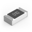
 | 560112116091 | SPEC | 7 files | Active i| Production is active. Expected lifetime: >10 years. | WRIS-RSKS Thick Film Resistors | – | – | – | – | – | – | – | – | – | – | – | – | – | – | – | – | – | – | – | – | – | – | 0603 | -55 °C up to +155 °C | – | – | – | – | 1.6 | 0.8 | 0.45 | – | 2 kΩ | ±1% | 0.1 | -100 | 100 | 75 | SMT | – | – |
| Samples |
|---|
| Order Code | Datasheet | Simulation | Downloads | Status | Product series | λDom typ. (nm) | Emitting Color | λPeak typ. (nm) | IV typ. (mcd) | VF typ. (V) | Chip Technology | 2θ50% typ. (°) | Gender | Pins | Type | Wire Section | Contact Plating | IR (A) | Working Voltage (V (AC)) | Contact Resistance (mΩ) | Packaging | Qty. (pcs) | Stranded Wire Section (AWG) | Stranded Wire Section (Metric) | C | Tol. C | VR (V (DC)) | Size | Operating Temperature | Q (%) | DF (%) | RISO | Ceramic Type | L (mm) | W (mm) | H (mm) | Fl (mm) | R | Tol. R | PRated (W) | TCR (ppm/ °C) | TCR (ppm/ °C) | VE (V) | Mount | IR (A) | PCB/Cable/Panel | Samples |
|---|


