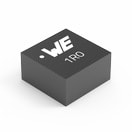
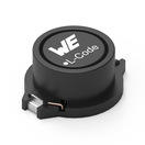
WE-HCMD High Current Inductor for TLVR ApplicationsEXTENDED
ShieldedL1 70 to 200 nHIRP,1 78 A
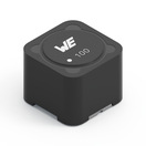
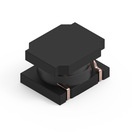
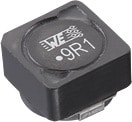
WE-HCM SMT High Current Flat Wire Inductor
ShieldedL 0.025 to 1.5 µHIR 23 to 70 A
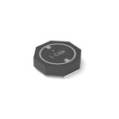
WE-LQSH SMT High Saturation Power Inductor
Semi ShieldedL 0.47 to 10 µHIR 0.58 to 4.5 A
WE-LQFS SMT Power Inductor
ShieldedL 1 to 470 µHIR 0.26 to 4.47 A
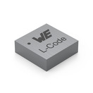
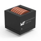
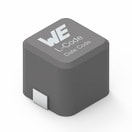
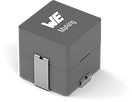
WE-HCC SMT High Current Cube Inductor
ShieldedL 0.22 to 10 µHIR 11.5 to 27 A
WE-HEPC SMT Power Inductor
ShieldedL 3.3 to 100 µHIR 0.5 to 2 A
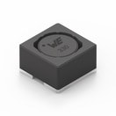
WE-SPC SMT Power Inductor
ShieldedL 0.22 to 100 µHIR 0.4 to 5.3 A
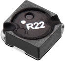
WE-PD2SR Power Inductor
ShieldedL 1.2 to 220 µHIR 0.67 to 4.85 A
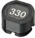
WE-PD3 SMT Power Inductor
ShieldedL 1 to 1000 µHIR 0.19 to 3.9 A
WE-PDF SMT Power Inductor
ShieldedL 0.22 to 27 µHIR 4.3 to 19 A
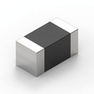
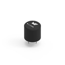
WE-PMI Power Multilayer Inductor
ShieldedL 0.22 to 10 µHIR 450 to 2000 mA
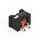
WE-HIDA THT High Current Inductor
Digital AudioL 8.2 to 22 µHIR 5.7 to 19 A
WE-LHMD SMT High Current Inductor
Digital AudioL 8.2 to 22 µHIR 2 to 7 A
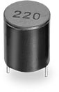
WE-TIS Radial Leaded Wire Wound Inductor
ShieldedL 1 to 8200 µHIR 0.1 to 10.5 A
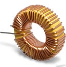
WE-SI Leaded Toroidal Storage Choke
ShieldedL 12 to 1619 µHIR 1.1 to 14.5 A
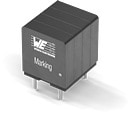
WE-FAMI THT Power Inductor
ShieldedL 3 to 22 µHIR 3.7 to 14.5 A
Rated Current
This value describes the direct current at which the component self heating increases by 40 Kelvin. ∆T = 40K
The method Würth Elektronik uses to measure the rated current is based upon section 6 of the IEC 62024-2:2020 standard to provide transparent and comparable IR values. A test PCB with a soldered Power Inductor is contained within a box of roughly 40 cm on each side. The Component and the PCB do not contact directly with the surrounding box. Only natural heat exchange occurs, with no forced heat transfer e.g. airflow, applied to the test PCB.
They are different methods to measure the temperature. Würth Elektronik decided to use an infrared camera to reliably detect and measure the hottest area of the component. In order to prevent measurement error, the test PCB is prepared with a black coating.
To determine the 40 K self-heating mentioned above, the current flowing through the component is increased step by step. The temperature is considered to have stabilized as soon as the heating is reduced to less than 1 K per minute during a current step. The time it takes for the temperature to stabilize also depends on the volume and material composition of the inductor.
Influence of PCB Trace Dimensions on Rated Current
The self-heating of the power inductor is influenced by the dimensions of the conductor traces on which it is soldered.
A small conductor trace cross-section is less able to transport heat. The power inductor can therefore only dissipate the heat from the current via the air. The self-heating of 40 K is already achieved at a low current.
A larger cross-sectional area reduces the thermal resistance. Wide conductor traces with a large copper surface increase the heat flow, which means that the inductance can dissipate the self-heating better via the conductor traces. The component can be operated with higher currents as the self-heating of 40 K is only achieved at a higher current.
Rated Current & Performance Rated Current
In some datasheets there is more than one Rated current specified.
The Rated Current is measured without the IEC standard.
The Performane Rated Current is measured by using the conditions specified in the IEC standard.
Due to the range of sizes and construction types of the Würth Elektronik product line-up, different PCB layouts are used to measure the rated current.
The WE-legacy PCB are used to measre the rated current as defined in some datasheet whereas the Performance Rated Current in the datasheet is measured by using the Iclass PCBs.
IR = WE-LHMI measured on the WE legacy PCB, IRP = WE-LHMI measured on IIclass C PCB, 5 mm = WE-LHMI measured on 5 mm trace width, FC: Forced Convection
Different PCBs and forced convection influence the rated current.
Lack of transparency about the test conditions makes it difficult to compare different rated currents data.
Würth Elektronik avoids this issue by using the IEC Standard.
Rated Current Calculator in REDEXPERT
Rated Current Calculator in REDEXPERT
In order to define the rated current for components when measured on different sized PCB conductor traces, Würth Elektronik now has online Rated Current Calculator available through REDEXPERT which allows the user to input the desired copper conductor dimensions.
Get a quick and easy overview of the different current ranges, mounting styles and product areas with our storage applications guide and quickly select the right component for your application.
Würth Elektronik employs transparent measurement methods in accordance with Section 6 of the IEC 62024-2:2020 standard to determine the rated current (Ir) for temperature rise in power inductors. Utilizing a 20 cm test PCB within a box, natural convection occurs without direct contact with the surrounding box. Instead of a thermocouple, an infrared camera is used to avoid measurement errors and capture the hottest external point of the core. Temperature stabilizes during current passage at less than 1 °C per minute.