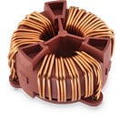
WE-CMBNC Common Mode Power Line Choke Nanocrystalline
L 0.4 to 190 mHIR 0.6 to 38 ARDC max. 1.1 to 1000 mΩ
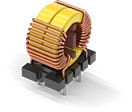
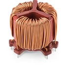
WE-CMB Common Mode Power Line Choke
L 0.5 to 39 mHIR 0.3 to 35 ARDC max. 2.3 to 3000 mΩ
WE-CMB HC Common Mode Power Line Choke
L 0.175 to 0.7 mHIR 5 to 8 ARDC max. 6 to 15 mΩ
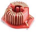
WE-CMB HV Common Mode Power Line Choke
L 0.7 to 4.7 mHIR 6.8 to 21.5 ARDC max. 3.8 to 44 mΩ
WE-CMB NiZn Common Mode Power Line Choke
L 14 to 110 µHIR 1.5 to 10 ARDC max. 3 to 80 mΩ
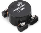
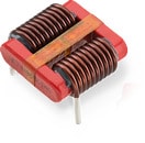
WE-ExB Common Mode Power Line Choke
L 47 to 1000 µHIR 4.5 to 15 ARDC max. 4.6 to 42 mΩ
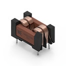
WE-CMBH Common Mode Power Line Choke (Horizontal)
L 1 to 20 mHIR 2 to 10 ARDC max. 12.5 to 230 mΩ
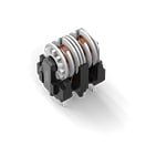
WE-LF Common Mode Power Line Choke
L 0.4 to 50 mHIR 0.3 to 6 ARDC max. 0.02 to 2.6 Ω
WE-LF SMT Common Mode Power Line Choke
L 0.7 to 47 mHIR 0.4 to 5.25 ARDC max. 0.03 to 2.6 Ω
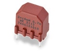
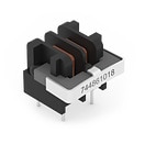
WE-TFC Common Mode Power Line Choke
L 1.8 to 25 mHIR 0.25 to 1 ARDC max. 0.31 to 3.6 Ω
WE-FC Common Mode Power Line Choke
L 1.1 to 43 mHIR 0.4 to 2.65 ARDC max. 0.08 to 2.88 Ω
WE-LPCC Common Mode Power Line Choke
L 120 to 450 µHIR 9.5 to 23.5 ARDC max. 1.4 to 9.6 mΩ
WE-FCLP Common Mode Power Line Choke
L 6 to 100 mHRDC max. 220 to 3470 mΩ
WE-TPB HV Three-Phase Common Mode Power Line Choke
L 0.2 to 208 mHIR 7.2 to 46 ARDC max. 1.6 to 85 mΩ
WE-TPB Three-Phase Common Mode Power Line Choke
L 0.52 to 12 mHIR 6 to 24 A
Filter and Material Behavior
Common mode chokes with dual winding chambers are charatcerized by a higher attenuation maximum compared to those with a single winding chamber. At the same time, this attenuation maximum is shifted to higher frequencies.
By choosing the right core material for common mode chokes, the desired attenuation curve depending on the frequency can be chosen. While manganese-zinc has its attenuation maximum at lower frequencies, it is higher for nickel-zinc. Nanocrystalline core material and the combination of manganese-zinc with nickel-zinc exhibit broader attenuation behavior.