IC manufacturers (105)
- All manufacturers
 Analog Devices
 Infineon Technologies
 Microchip
 Onsemi
 Renesas
 ROHM
ROHM STMicroelectronics
 Texas Instruments
- 3peak incorporated (35)
- Ablic (23)
- Acco Semiconductor (1)
- Advanced Power (4)
- Allegro Microsystems (100)
- Alpha & Omega Semiconductor (37)
- AnalogySemi (3)
- AnDAPT Inc (204)
- Anpec (13)
- AXElite (2)
- Backward (6)
- Bright Power Semiconductor (1)
- Broadcom (46)
- Cambridge GaN Devices (18)
- Chipanalog Micro (10)
- Cologne Chips (1)
- Convenient Power (1)
- Dialog Semiconductor (12)
- Diodes Incorporated (257)
- Divimath (8)
- Elmos AG (1)
- EPC (146)
- e-Peas Semiconductors (1)
- Eta Solutions Co. Ltd. (9)
- GaN Systems (8)
- GaNPower (3)
- Giantec (1)
- Gstek Wuxi (1)
- Helix Semiconductor (7)
- IKON (1)
- Indie Semiconductor (8)
- Innovision Semiconductor Inc (2)
- Intel (68)
- Inventchip Technology (3)
- ISSI (51)
- JoulWatt (20)
- KDPOF (3)
- Kinetic Technology (8)
- Lattice semiconductor Corporation (38)
- Littelfuse (1)
- Lumissil Microsystems (8)
- M3 Technology (M3Tek) (7)
- Macnica (22)
- Marvell Semiconductor (1)
- MaxLinear (181)
- Menlo Micro (1)
- MikroE (25)
- MindCet (2)
- Monolithic Power Systems (982)
- Navitas Semiconductor Inc (6)
- NewEdge Technologies, Inc. (1)
- Nexperia (268)
- Nisshinbo Micro Device Inc. (10)
- Nordic Semiconductor (1)
- Novosense Micro (1)
- NXP (341)
- O2 Micro International Ltd (10)
- On Bright (7)
- Panasonic (2)
- PN Junction Semiconductor (2)
- Power Integrations (117)
- Powermat (1)
- Pulsiv (19)
- Qorvo (99)
- Realsil SuRealsil(tek) Microelectronics (1)
- Richtek (297)
- Sanken Electric Co., Ltd. (16)
- Sckipio (6)
- Semtech (86)
- SG-Micro (58)
- SiFive (2)
- Silanna Semiconductor (9)
- Silergy Corporation (34)
- Silicon Laboratory Inc. (108)
- Silicontent Technology (59)
- Silvertel (59)
- Skycore Semiconductors (1)
- Skyworks (33)
- Southchip (18)
- Summit Wireless (1)
- Tagore Tech (7)
- Taiwan Semiconductor (1)
- TDK Corporation (1)
- Tempo Semiconductor (1)
- Torex (37)
- Toshiba (27)
- Transphorm (21)
- TransSIP (2)
- Union (21)
- uPI Semiconductor (2)
- Valens Semiconductor (31)
- VisIC (1)
- Wise Integration (3)
- Wolfspeed (23)
- Xilinx (22)
- XL Semiconductor (3)
- XYSemi (62)
Overview
| Topology | Other Topology |
| Input voltage | 12-36 V |
| IC revision | 1.0 |
Description
The X-NUCLEO-OUT17A1 is an industrial digital output expansion board for STM32 Nucleo. It provides a powerful and flexible environment for the evaluation of the driving and diagnostic capabilities of the IPS8200HQ-1 octal high-side, smart power, solid-state relay in a digital output module connected to 1.0 A industrial loads.The X-NUCLEO-OUT17A1 interfaces with the microcontroller on the STM32 Nucleo via STISO620 and STISO621 and Arduino® UNO R3 connectors.The user can select which driving mode controls the IPS8200HQ-1: parallel (SEL2 = L by JP21 = open) or SPI (SEL2 = H by JP21 = closed).In the case of SPI selection, the user can select the communication protocol between 8 bits (SEL1 = L by JP22 = open) or 16 bits (SEL1 = H by JP22 = closed).The VCC supply pin of the IPS8200HQ-1 is provided by the connector CN1, while the loads (driven by the 8 output channels of the IPS8200HQ-1) can be connected between the connectors CN2, CN3, CN4, CN12, and the pin 2 of the connector CN1.The on-board digital isolators (STISO620 and STISO621) feature the 2.8k VRMS (4k VPK) galvanic isolation between the two application sides: logic and process sides.The logic side is the application side of the MCU and it is supplied by the VISO_L rail (3.3 or 5.0 V). VISO_L can be supplied by an external power supply connected to CN13 or, alternatively by the pin 4 (SW1 = close 1-2) or pin 5 (SW1 = close 2-3) of CN6.The process side is the application side of the industrial loads and it is supplied by the VCC and VISO_P rails. The VISO_P (3.3 or 5.0 V) is usually supplied by the VREG rail (JP31 = closed) that can be generated by the step-down embedded in the IPS8200HQ-1 (SW17 = close 1-2, JP20 = closed, JP15 = closed and JP28 = close 2-4 (VREG = 3.3 V) or JP28 = 1-3 (VREG = 5.0 V)).Alternatively, VREG can be provided by an external power supply connected to CN14 (SW17 = close 2-3, JP20 = open, JP15 = open).In parallel driving mode (active with the default jumper and switch settings) the application board can work even without any Nucleo board: in this case, the user must provide the process side voltage (usually 24 V) by the CN1 and the VISO_L (usually 3.3 V) by the CN13. The INX signals, available on CN5[1, 2, 3], CN8[4] and CN9[3, 5, 7, 8], drives on/off the correspondent OUTX connected to the loads on the process side.The INX pins can be driven low/high swinging between 0V and VISO_L. The activation of each OUTX (OUT1… OUT8) can be monitored by the green LEDs DOX (DO1… DO8).The activation of the three diagnostic pins (TWARN, PGOOD, FAULT) can be visualized on the correspondent red LEDs (D11, D12, D13, respectively) or monitored by an oscilloscope on CN8[5], CN5[9], CN5[10].The SPI driving mode can be set by changing the default configuration (JP21 = close; SW4, SW5, SW6, SW7, SW9, SW10, SW11, SW12, SW13, SW14, SW15, SW20 = close 2-3, SW18 = close 1-2). The SPI-8bits is the default mode (JP22 = open), while the SPI-16bits mode can be activated by JP22 = close.In SPI driving mode it is also possible to activate the MCU freeze detection feature by setting SW3 = close 2-3.The expansion board can be connected to either a NUCLEO-F401RE or a NUCLEO-G431RB development board. In this case the companion firmware X-CUBE-IPS detects the selected configuration (GPIO, SPI-8bits, SPI-16bits) by reading the signals SEL2_L and SEL1 from CN8[1] and CN8[6]. The activation of the MCU freeze feature is detected by WDEN(in) on CN9[4].It is also possible to evaluate a system composed of a X-NUCLEO-OUT17A1 stacked on other expansion boards. In fact, SPI driving mode allows the daisy-chaining communication with another X-NUCLEO-OUT17A1 stacked through the Arduino connectors: the two stacked boards must be configured with SW6, SW18 = close 2-3 on one board, and SW6, SW18 = close 1-2 on the other board.
Features
Based on the IPS8200HQ-1 octal high-side switch, which features:Operating range 10.5 to 36 VOperating output current ≤ 1.0 ALow-power dissipation (RUndervoltage lock-outSelectable driving modes parallel or 5 MHz SPI (8 or 16 bits)Embedded step-down converter4x2 LED matrix for efficient status indicationMCU freeze detectionFast decay for inductive loadsOverload and overtemperature protectionsLoss of ground protectionJunction overtemperature and parity check diagnostic pin (FAULT)Case overtemperature diagnostic pin (TWARN)Supply voltage level diagnostic pin (PGOOD)QFN48L 8x6 mm packageApplication board operating range: 12 to 33 VExtended voltage operating range (J9 open) up to 36 VOperating current: up to 1.0 A per channelBlue LED showing SPI mode selectionYellow LED showing SPI mode 16-bits selectionRed LED for FAULT diagnostic pin (JP12 closed)Red LED for PGOOD diagnostic pin (JP13 closed)Red LED for TWARN diagnostic pin (JP27 closed)4 kVPK galvanic isolation ensured by STISO620 and STISO621Supply rail reverse polarity protectionCompatible with STM32 Nucleo development boardsEquipped with Arduino® UNO R3 connectorsCE certifiedRoHS and China RoHS compliant
Typical applications
- Industrial digital output expansion board
More information
Products
Order Code | Datasheet | Simulation | Downloads | Status | Product series | Pins | Application | PCB/Cable/Panel | Modularity | Type | Wire Section | λDom typ.(nm) | Emitting Color | λPeak typ.(nm) | IV typ.(mcd) | VF typ.(V) | Chip Technology | 2θ50% typ.(°) | C | Tol. C | VR(V (DC)) | Size | Operating Temperature | DF(%) | RISO | L(mm) | W(mm) | H(mm) | Fl(mm) | Ceramic Type | Packaging | Q | L(µH) | IR(A) | ISAT(A) | fres(MHz) | Mount | Endurance(h) | IRIPPLE(mA) | ILeak(µA) | Pitch(mm) | Ø D(mm) | Working Voltage(V (AC)) | Color | Gender | SamplesAvailability & Sample | ||||||||||||||||||||||||||||||||||||||||||||||||||||||||||||||||||||||||||||||||||||||||||||||||||||||||||||||||||||||||||||||||||||||||||||||||||||||||||||||||||||||||||||||||||||||||||||||||||||||||||||||||||||||||||||||||||||||||||||||||||||||||||||||||||||||||||||||||||||||||||||||||||||||||||||||||||||||||||||||||||||||||||||||||||||||||||||||||||||||||||||||||||||||||||||||||||||||||||||||||||||||||||||||||||||||||||||||||||||||||||||||||||||||||||||||||||||||||||||||||||||||||||||||||||||||||||||||||||||||||||||||||||||||||||||||||||||||||||||||||||||||||||||||||||||||||||||||||||||||||||||||||||||||||||||||||||||||||||||||||||||||||||||||||||||||||||||||||||||||||||||||||||||||||||||||||||||||||||||||||||||||||||||||||||||||||||||||||||||||||||||||||||||||||||||||||||||||||||||||||||||||||||||||||||||||||||||||||||||||||||||||||||||||||||||||||||||||||||||||||||||||||||||||||||||||||||||||||||||||||||||||||||||||||||||||||||||||||
|---|---|---|---|---|---|---|---|---|---|---|---|---|---|---|---|---|---|---|---|---|---|---|---|---|---|---|---|---|---|---|---|---|---|---|---|---|---|---|---|---|---|---|---|---|---|---|---|---|---|---|---|---|---|---|---|---|---|---|---|---|---|---|---|---|---|---|---|---|---|---|---|---|---|---|---|---|---|---|---|---|---|---|---|---|---|---|---|---|---|---|---|---|---|---|---|---|---|---|---|---|---|---|---|---|---|---|---|---|---|---|---|---|---|---|---|---|---|---|---|---|---|---|---|---|---|---|---|---|---|---|---|---|---|---|---|---|---|---|---|---|---|---|---|---|---|---|---|---|---|---|---|---|---|---|---|---|---|---|---|---|---|---|---|---|---|---|---|---|---|---|---|---|---|---|---|---|---|---|---|---|---|---|---|---|---|---|---|---|---|---|---|---|---|---|---|---|---|---|---|---|---|---|---|---|---|---|---|---|---|---|---|---|---|---|---|---|---|---|---|---|---|---|---|---|---|---|---|---|---|---|---|---|---|---|---|---|---|---|---|---|---|---|---|---|---|---|---|---|---|---|---|---|---|---|---|---|---|---|---|---|---|---|---|---|---|---|---|---|---|---|---|---|---|---|---|---|---|---|---|---|---|---|---|---|---|---|---|---|---|---|---|---|---|---|---|---|---|---|---|---|---|---|---|---|---|---|---|---|---|---|---|---|---|---|---|---|---|---|---|---|---|---|---|---|---|---|---|---|---|---|---|---|---|---|---|---|---|---|---|---|---|---|---|---|---|---|---|---|---|---|---|---|---|---|---|---|---|---|---|---|---|---|---|---|---|---|---|---|---|---|---|---|---|---|---|---|---|---|---|---|---|---|---|---|---|---|---|---|---|---|---|---|---|---|---|---|---|---|---|---|---|---|---|---|---|---|---|---|---|---|---|---|---|---|---|---|---|---|---|---|---|---|---|---|---|---|---|---|---|---|---|---|---|---|---|---|---|---|---|---|---|---|---|---|---|---|---|---|---|---|---|---|---|---|---|---|---|---|---|---|---|---|---|---|---|---|---|---|---|---|---|---|---|---|---|---|---|---|---|---|---|---|---|---|---|---|---|---|---|---|---|---|---|---|---|---|---|---|---|---|---|---|---|---|---|---|---|---|---|---|---|---|---|---|---|---|---|---|---|---|---|---|---|---|---|---|---|---|---|---|---|---|---|---|---|---|---|---|---|---|---|---|---|---|---|---|---|---|---|---|---|---|---|---|---|---|---|---|---|---|---|---|---|---|---|---|---|---|---|---|---|---|---|---|---|---|---|---|---|---|---|---|---|---|---|---|---|---|---|---|---|---|---|---|---|---|---|---|---|---|---|---|---|---|---|---|---|---|---|---|---|---|---|---|---|---|---|---|---|---|---|---|---|---|---|---|---|---|---|---|---|---|---|---|---|---|---|---|---|---|---|---|---|---|---|---|---|---|---|---|---|---|---|---|---|---|---|---|---|---|---|---|---|---|---|---|---|---|---|---|---|---|---|---|---|---|---|---|---|---|---|---|---|---|---|---|---|---|---|---|---|---|---|---|---|---|---|---|---|---|---|---|---|---|---|---|---|---|---|---|---|---|---|---|---|---|---|---|---|---|---|---|---|---|---|---|---|---|---|---|---|---|---|---|---|---|---|---|---|---|---|---|---|---|---|---|---|---|---|---|---|---|---|---|---|---|---|---|---|---|---|---|---|---|---|---|---|---|---|---|---|---|---|---|---|---|---|---|---|---|---|---|---|---|---|---|---|---|---|---|---|---|---|---|---|---|---|---|---|---|---|---|---|---|---|---|---|---|---|---|---|---|---|---|---|---|---|---|---|---|---|---|---|---|---|---|---|---|---|---|---|---|---|---|---|---|---|---|---|---|---|---|---|---|---|---|---|---|---|---|---|---|---|---|---|---|---|---|---|---|---|---|---|---|---|---|---|---|---|---|---|---|---|---|---|---|---|---|---|---|---|---|---|---|---|---|---|---|---|---|---|---|---|---|---|---|---|---|---|---|---|---|---|---|---|---|---|---|---|---|---|---|---|---|---|---|---|---|---|---|---|---|---|---|---|---|---|---|---|---|---|---|---|---|---|---|---|---|---|---|---|---|---|---|---|---|---|---|---|---|---|---|---|---|---|---|---|---|---|---|---|---|---|---|---|---|---|---|---|---|---|---|---|---|---|---|---|---|---|---|---|---|---|---|---|---|---|---|---|---|---|---|---|---|---|---|---|---|
| Log in now to view availability and request availability forecasts. LOGIN | ||||||||||||||||||||||||||||||||||||||||||||||||||||||||||||||||||||||||||||||||||||||||||||||||||||||||||||||||||||||||||||||||||||||||||||||||||||||||||||||||||||||||||||||||||||||||||||||||||||||||||||||||||||||||||||||||||||||||||||||||||||||||||||||||||||||||||||||||||||||||||||||||||||||||||||||||||||||||||||||||||||||||||||||||||||||||||||||||||||||||||||||||||||||||||||||||||||||||||||||||||||||||||||||||||||||||||||||||||||||||||||||||||||||||||||||||||||||||||||||||||||||||||||||||||||||||||||||||||||||||||||||||||||||||||||||||||||||||||||||||||||||||||||||||||||||||||||||||||||||||||||||||||||||||||||||||||||||||||||||||||||||||||||||||||||||||||||||||||||||||||||||||||||||||||||||||||||||||||||||||||||||||||||||||||||||||||||||||||||||||||||||||||||||||||||||||||||||||||||||||||||||||||||||||||||||||||||||||||||||||||||||||||||||||||||||||||||||||||||||||||||||||||||||||||||||||||||||||||||||||||||||||||||||||||||||||||||||||||||||||||||||||||||||||||||||||||||||||||||||
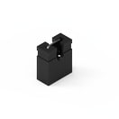 | SPECWR-PHD Jumper, 1, – | Simulation– | Availability – | Status Activei| Production is active. Expected lifetime: >10 years. | Product seriesWR-PHD Jumper | Pins1 | – | – | – | – | – | – | – | – | – | – | – | – | – | – | – | – | Operating Temperature -40 °C up to +125 °C | – | Insulation Resistance1000 MΩ | Length2.44 mm | – | – | – | – | PackagingBag | – | – | Rated Current3 A | – | – | – | – | – | – | Pitch2.54 mm | – | Working Voltage250 V (AC) | ColorBlack | GenderJumper | –Check availability | ||||||||||||||||||||||||||||||||||||||||||||||||||||||||||||||||||||||||||||||||||||||||||||||||||||||||||||||||||||||||||||||||||||||||||||||||||||||||||||||||||||||||||||||||||||||||||||||||||||||||||||||||||||||||||||||||||||||||||||||||||||||||||||||||||||||||||||||||||||||||||||||||||||||||||||||||||||||||||||||||||||||||||||||||||||||||||||||||||||||||||||||||||||||||||||||||||||||||||||||||||||||||||||||||||||||||||||||||||||||||||||||||||||||||||||||||||||||||||||||||||||||||||||||||||||||||||||||||||||||||||||||||||||||||||||||||||||||||||||||||||||||||||||||||||||||||||||||||||||||||||||||||||||||||||||||||||||||||||||||||||||||||||||||||||||||||||||||||||||||||||||||||||||||||||||||||||||||||||||||||||||||||||||||||||||||||||||||||||||||||||||||||||||||||||||||||||||||||||||||||||||||||||||||||||||||||||||||||||||||||||||||||||||||||||||||||||||||||||||||||||||||||||||||||||||||||||||||||||||||||||||||||||||||||||||||||||||||||
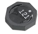 | SPECWE-TPC SMT Tiny Power Inductor, 2, – | Availability – | Status Activei| Production is active. Expected lifetime: >10 years. | Product seriesWE-TPC SMT Tiny Power Inductor | Pins2 | – | – | – | – | – | – | – | – | – | – | – | – | – | – | – | Size1028 | Operating Temperature -40 °C up to +125 °C | – | – | Length10 mm | Width10 mm | Height2.8 mm | – | – | – | – | Inductance100 µH | Rated Current1 A | Saturation Current0.9 A | Self Resonant Frequency7 MHz | MountSMT | – | – | – | – | – | – | – | – | –Check availability | |||||||||||||||||||||||||||||||||||||||||||||||||||||||||||||||||||||||||||||||||||||||||||||||||||||||||||||||||||||||||||||||||||||||||||||||||||||||||||||||||||||||||||||||||||||||||||||||||||||||||||||||||||||||||||||||||||||||||||||||||||||||||||||||||||||||||||||||||||||||||||||||||||||||||||||||||||||||||||||||||||||||||||||||||||||||||||||||||||||||||||||||||||||||||||||||||||||||||||||||||||||||||||||||||||||||||||||||||||||||||||||||||||||||||||||||||||||||||||||||||||||||||||||||||||||||||||||||||||||||||||||||||||||||||||||||||||||||||||||||||||||||||||||||||||||||||||||||||||||||||||||||||||||||||||||||||||||||||||||||||||||||||||||||||||||||||||||||||||||||||||||||||||||||||||||||||||||||||||||||||||||||||||||||||||||||||||||||||||||||||||||||||||||||||||||||||||||||||||||||||||||||||||||||||||||||||||||||||||||||||||||||||||||||||||||||||||||||||||||||||||||||||||||||||||||||||||||||||||||||||||||||||||||||||||||||||||||||||
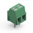 | SPECWR-TBL Series 2141 - 3.50 mm Horiz. Entry Modular, 2, Rising Cage Clamp | Simulation– | Availability – | Downloads7 files | Status Activei| Production is active. Expected lifetime: >10 years. | Product seriesWR-TBL Series 2141 - 3.50 mm Horiz. Entry Modular | Pins2 | ApplicationRising Cage Clamp | PCB/Cable/PanelPCB | ModularityYes | TypeHorizontal | Wire Section 24 to 16 (AWG) 0.2 to 1 (mm²) | – | – | – | – | – | – | – | – | – | – | – | Operating Temperature -40 °C up to +105 °C | – | – | Length7.05 mm | – | – | – | – | PackagingBox | – | – | Rated Current10 A | – | – | MountTHT | – | – | – | Pitch3.5 mm | – | Working Voltage300 V (AC) | – | – | –Check availability | |||||||||||||||||||||||||||||||||||||||||||||||||||||||||||||||||||||||||||||||||||||||||||||||||||||||||||||||||||||||||||||||||||||||||||||||||||||||||||||||||||||||||||||||||||||||||||||||||||||||||||||||||||||||||||||||||||||||||||||||||||||||||||||||||||||||||||||||||||||||||||||||||||||||||||||||||||||||||||||||||||||||||||||||||||||||||||||||||||||||||||||||||||||||||||||||||||||||||||||||||||||||||||||||||||||||||||||||||||||||||||||||||||||||||||||||||||||||||||||||||||||||||||||||||||||||||||||||||||||||||||||||||||||||||||||||||||||||||||||||||||||||||||||||||||||||||||||||||||||||||||||||||||||||||||||||||||||||||||||||||||||||||||||||||||||||||||||||||||||||||||||||||||||||||||||||||||||||||||||||||||||||||||||||||||||||||||||||||||||||||||||||||||||||||||||||||||||||||||||||||||||||||||||||||||||||||||||||||||||||||||||||||||||||||||||||||||||||||||||||||||||||||||||||||||||||||||||||||||||||||||||||||||||||||||||||||||||||
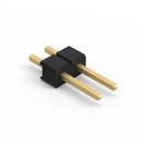 | SPECWR-PHD Pin Header - Single, 2, – | Simulation– | Availability – | Status Activei| Production is active. Expected lifetime: >10 years. | Product seriesWR-PHD Pin Header - Single | Pins2 | – | – | – | TypeStraight | – | – | – | – | – | – | – | – | – | – | – | – | Operating Temperature -40 °C up to +105 °C | – | Insulation Resistance1000 MΩ | Length5.08 mm | – | – | – | – | PackagingBag | – | – | Rated Current3 A | – | – | MountTHT | – | – | – | Pitch2.54 mm | – | Working Voltage250 V (AC) | – | GenderPin Header | –Check availability | ||||||||||||||||||||||||||||||||||||||||||||||||||||||||||||||||||||||||||||||||||||||||||||||||||||||||||||||||||||||||||||||||||||||||||||||||||||||||||||||||||||||||||||||||||||||||||||||||||||||||||||||||||||||||||||||||||||||||||||||||||||||||||||||||||||||||||||||||||||||||||||||||||||||||||||||||||||||||||||||||||||||||||||||||||||||||||||||||||||||||||||||||||||||||||||||||||||||||||||||||||||||||||||||||||||||||||||||||||||||||||||||||||||||||||||||||||||||||||||||||||||||||||||||||||||||||||||||||||||||||||||||||||||||||||||||||||||||||||||||||||||||||||||||||||||||||||||||||||||||||||||||||||||||||||||||||||||||||||||||||||||||||||||||||||||||||||||||||||||||||||||||||||||||||||||||||||||||||||||||||||||||||||||||||||||||||||||||||||||||||||||||||||||||||||||||||||||||||||||||||||||||||||||||||||||||||||||||||||||||||||||||||||||||||||||||||||||||||||||||||||||||||||||||||||||||||||||||||||||||||||||||||||||||||||||||||||||||||
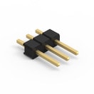 | SPECWR-PHD Pin Header - Single, 3, – | Simulation– | Availability – | Status Activei| Production is active. Expected lifetime: >10 years. | Product seriesWR-PHD Pin Header - Single | Pins3 | – | – | – | TypeStraight | – | – | – | – | – | – | – | – | – | – | – | – | Operating Temperature -40 °C up to +105 °C | – | Insulation Resistance1000 MΩ | Length7.62 mm | – | – | – | – | PackagingBag | – | – | Rated Current3 A | – | – | MountTHT | – | – | – | Pitch2.54 mm | – | Working Voltage250 V (AC) | – | GenderPin Header | –Check availability | ||||||||||||||||||||||||||||||||||||||||||||||||||||||||||||||||||||||||||||||||||||||||||||||||||||||||||||||||||||||||||||||||||||||||||||||||||||||||||||||||||||||||||||||||||||||||||||||||||||||||||||||||||||||||||||||||||||||||||||||||||||||||||||||||||||||||||||||||||||||||||||||||||||||||||||||||||||||||||||||||||||||||||||||||||||||||||||||||||||||||||||||||||||||||||||||||||||||||||||||||||||||||||||||||||||||||||||||||||||||||||||||||||||||||||||||||||||||||||||||||||||||||||||||||||||||||||||||||||||||||||||||||||||||||||||||||||||||||||||||||||||||||||||||||||||||||||||||||||||||||||||||||||||||||||||||||||||||||||||||||||||||||||||||||||||||||||||||||||||||||||||||||||||||||||||||||||||||||||||||||||||||||||||||||||||||||||||||||||||||||||||||||||||||||||||||||||||||||||||||||||||||||||||||||||||||||||||||||||||||||||||||||||||||||||||||||||||||||||||||||||||||||||||||||||||||||||||||||||||||||||||||||||||||||||||||||||||||||
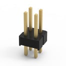 | SPECWR-PHD Pin Header - Dual, 4, – | Simulation– | Availability – | Status Activei| Production is active. Expected lifetime: >10 years. | Product seriesWR-PHD Pin Header - Dual | Pins4 | – | – | – | TypeStraight | – | – | – | – | – | – | – | – | – | – | – | – | Operating Temperature -40 °C up to +105 °C | – | Insulation Resistance1000 MΩ | Length5.08 mm | – | – | – | – | PackagingBag | – | – | Rated Current3 A | – | – | MountTHT | – | – | – | Pitch2.54 mm | – | Working Voltage250 V (AC) | – | GenderPin Header | –Check availability | ||||||||||||||||||||||||||||||||||||||||||||||||||||||||||||||||||||||||||||||||||||||||||||||||||||||||||||||||||||||||||||||||||||||||||||||||||||||||||||||||||||||||||||||||||||||||||||||||||||||||||||||||||||||||||||||||||||||||||||||||||||||||||||||||||||||||||||||||||||||||||||||||||||||||||||||||||||||||||||||||||||||||||||||||||||||||||||||||||||||||||||||||||||||||||||||||||||||||||||||||||||||||||||||||||||||||||||||||||||||||||||||||||||||||||||||||||||||||||||||||||||||||||||||||||||||||||||||||||||||||||||||||||||||||||||||||||||||||||||||||||||||||||||||||||||||||||||||||||||||||||||||||||||||||||||||||||||||||||||||||||||||||||||||||||||||||||||||||||||||||||||||||||||||||||||||||||||||||||||||||||||||||||||||||||||||||||||||||||||||||||||||||||||||||||||||||||||||||||||||||||||||||||||||||||||||||||||||||||||||||||||||||||||||||||||||||||||||||||||||||||||||||||||||||||||||||||||||||||||||||||||||||||||||||||||||||||||||||
 | SPECWR-PHD Pin Header - Dual, 8, – PCN pendingDue to a pending PCN, a modification of the component will be implemented soon. Please find the PCN below. If you have further questions please get in contact with our sales staff. | Simulation– | Availability – | Status Activei| Production is active. Expected lifetime: >10 years. | Product seriesWR-PHD Pin Header - Dual | Pins8 | – | – | – | TypeStraight | – | – | – | – | – | – | – | – | – | – | – | – | Operating Temperature -40 °C up to +105 °C | – | Insulation Resistance1000 MΩ | Length10.16 mm | – | – | – | – | PackagingBag | – | – | Rated Current3 A | – | – | MountTHT | – | – | – | Pitch2.54 mm | – | Working Voltage250 V (AC) | – | GenderPin Header | –Check availability | ||||||||||||||||||||||||||||||||||||||||||||||||||||||||||||||||||||||||||||||||||||||||||||||||||||||||||||||||||||||||||||||||||||||||||||||||||||||||||||||||||||||||||||||||||||||||||||||||||||||||||||||||||||||||||||||||||||||||||||||||||||||||||||||||||||||||||||||||||||||||||||||||||||||||||||||||||||||||||||||||||||||||||||||||||||||||||||||||||||||||||||||||||||||||||||||||||||||||||||||||||||||||||||||||||||||||||||||||||||||||||||||||||||||||||||||||||||||||||||||||||||||||||||||||||||||||||||||||||||||||||||||||||||||||||||||||||||||||||||||||||||||||||||||||||||||||||||||||||||||||||||||||||||||||||||||||||||||||||||||||||||||||||||||||||||||||||||||||||||||||||||||||||||||||||||||||||||||||||||||||||||||||||||||||||||||||||||||||||||||||||||||||||||||||||||||||||||||||||||||||||||||||||||||||||||||||||||||||||||||||||||||||||||||||||||||||||||||||||||||||||||||||||||||||||||||||||||||||||||||||||||||||||||||||||||||||||||||||
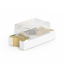 | SPECWL-SMCW SMT Mono-color Chip LED Waterclear, –, – | Availability – | Downloads27 files RAY files
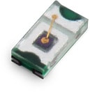
| Status Activei| Production is active. Expected lifetime: >10 years. | Product seriesWL-SMCW SMT Mono-color Chip LED Waterclear | – | – | – | – | – | – | Dominant Wavelength [typ.]625 nm | Emitting ColorRed | Peak Wavelength [typ.]630 nm | Luminous Intensity [typ.]250 mcd | Forward Voltage [typ.]2 V | Chip TechnologyAlInGaP | Viewing Angle Phi 0° [typ.]140 ° | – | – | – | Size0603 | Operating Temperature -40 °C up to +85 °C | – | – | Length1.6 mm | Width0.8 mm | Height0.7 mm | – | – | PackagingTape and Reel | – | – | – | – | – | MountSMT | – | – | – | – | – | – | – | – | –Check availability | ||||||||||||||||||||||||||||||||||||||||||||||||||||||||||||||||||||||||||||||||||||||||||||||||||||||||||||||||||||||||||||||||||||||||||||||||||||||||||||||||||||||||||||||||||||||||||||||||||||||||||||||||||||||||||||||||||||||||||||||||||||||||||||||||||||||||||||||||||||||||||||||||||||||||||||||||||||||||||||||||||||||||||||||||||||||||||||||||||||||||||||||||||||||||||||||||||||||||||||||||||||||||||||||||||||||||||||||||||||||||||||||||||||||||||||||||||||||||||||||||||||||||||||||||||||||||||||||||||||||||||||||||||||||||||||||||||||||||||||||||||||||||||||||||||||||||||||||||||||||||||||||||||||||||||||||||||||||||||||||||||||||||||||||||||||||||||||||||||||||||||||||||||||||||||||||||||||||||||||||||||||||||||||||||||||||||||||||||||||||||||||||||||||||||||||||||||||||||||||||||||||||||||||||||||||||||||||||||||||||||||||||||||||||||||||||||||||||||||||||||||||||||||||||||||||||||||||||||||||||||||||||||||||||||||||||||||||||||
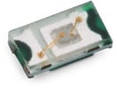
| SPECWL-SMCW SMT Mono-color Chip LED Waterclear, –, – | Availability – | Status Activei| Production is active. Expected lifetime: >10 years. | Product seriesWL-SMCW SMT Mono-color Chip LED Waterclear | – | – | – | – | – | – | Dominant Wavelength [typ.]570 nm | Emitting ColorBright Green | Peak Wavelength [typ.]572 nm | Luminous Intensity [typ.]40 mcd | Forward Voltage [typ.]2 V | Chip TechnologyAlInGaP | Viewing Angle Phi 0° [typ.]140 ° | – | – | – | Size0603 | Operating Temperature -40 °C up to +85 °C | – | – | Length1.6 mm | Width0.8 mm | Height0.7 mm | – | – | PackagingTape and Reel | – | – | – | – | – | MountSMT | – | – | – | – | – | – | – | – | –Check availability | |||||||||||||||||||||||||||||||||||||||||||||||||||||||||||||||||||||||||||||||||||||||||||||||||||||||||||||||||||||||||||||||||||||||||||||||||||||||||||||||||||||||||||||||||||||||||||||||||||||||||||||||||||||||||||||||||||||||||||||||||||||||||||||||||||||||||||||||||||||||||||||||||||||||||||||||||||||||||||||||||||||||||||||||||||||||||||||||||||||||||||||||||||||||||||||||||||||||||||||||||||||||||||||||||||||||||||||||||||||||||||||||||||||||||||||||||||||||||||||||||||||||||||||||||||||||||||||||||||||||||||||||||||||||||||||||||||||||||||||||||||||||||||||||||||||||||||||||||||||||||||||||||||||||||||||||||||||||||||||||||||||||||||||||||||||||||||||||||||||||||||||||||||||||||||||||||||||||||||||||||||||||||||||||||||||||||||||||||||||||||||||||||||||||||||||||||||||||||||||||||||||||||||||||||||||||||||||||||||||||||||||||||||||||||||||||||||||||||||||||||||||||||||||||||||||||||||||||||||||||||||||||||||||||||||||||||||||||||
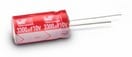 | SPECWCAP-ATUL Aluminum Electrolytic Capacitors, –, – | Availability – | Status Activei| Production is active. Expected lifetime: >10 years. | Product seriesWCAP-ATUL Aluminum Electrolytic Capacitors | – | – | – | – | – | – | – | – | – | – | – | – | – | Capacitance47 µF | Capacitance±20% | Rated Voltage100 V (DC) | – | – | Dissipation Factor9 % | – | Length12.5 mm | – | – | – | – | PackagingAmmopack | – | – | – | – | – | – | Endurance 7000 | Ripple Current400 mA | Leakage Current47 µA | Pitch5 mm | Diameter10 mm | – | – | – | –Check availability | |||||||||||||||||||||||||||||||||||||||||||||||||||||||||||||||||||||||||||||||||||||||||||||||||||||||||||||||||||||||||||||||||||||||||||||||||||||||||||||||||||||||||||||||||||||||||||||||||||||||||||||||||||||||||||||||||||||||||||||||||||||||||||||||||||||||||||||||||||||||||||||||||||||||||||||||||||||||||||||||||||||||||||||||||||||||||||||||||||||||||||||||||||||||||||||||||||||||||||||||||||||||||||||||||||||||||||||||||||||||||||||||||||||||||||||||||||||||||||||||||||||||||||||||||||||||||||||||||||||||||||||||||||||||||||||||||||||||||||||||||||||||||||||||||||||||||||||||||||||||||||||||||||||||||||||||||||||||||||||||||||||||||||||||||||||||||||||||||||||||||||||||||||||||||||||||||||||||||||||||||||||||||||||||||||||||||||||||||||||||||||||||||||||||||||||||||||||||||||||||||||||||||||||||||||||||||||||||||||||||||||||||||||||||||||||||||||||||||||||||||||||||||||||||||||||||||||||||||||||||||||||||||||||||||||||||||||||||||
SPECWCAP-CSGP MLCCs 10 V(DC), –, – | Availability – | Status Activei| Production is active. Expected lifetime: >10 years. | Product seriesWCAP-CSGP MLCCs 10 V(DC) | – | – | – | – | – | – | – | – | – | – | – | – | – | Capacitance4.7 pF | Capacitance±0.5pF | Rated Voltage10 V (DC) | Size0603 | Operating Temperature -55 °C up to +125 °C | – | Insulation Resistance10 GΩ | Length1.6 mm | Width0.8 mm | Height0.8 mm | Pad Dimension0.4 mm | Ceramic TypeNP0 Class I | Packaging7" Tape & Reel | Q-Factor494 | – | – | – | – | – | – | – | – | – | – | – | – | – | –Check availability | ||||||||||||||||||||||||||||||||||||||||||||||||||||||||||||||||||||||||||||||||||||||||||||||||||||||||||||||||||||||||||||||||||||||||||||||||||||||||||||||||||||||||||||||||||||||||||||||||||||||||||||||||||||||||||||||||||||||||||||||||||||||||||||||||||||||||||||||||||||||||||||||||||||||||||||||||||||||||||||||||||||||||||||||||||||||||||||||||||||||||||||||||||||||||||||||||||||||||||||||||||||||||||||||||||||||||||||||||||||||||||||||||||||||||||||||||||||||||||||||||||||||||||||||||||||||||||||||||||||||||||||||||||||||||||||||||||||||||||||||||||||||||||||||||||||||||||||||||||||||||||||||||||||||||||||||||||||||||||||||||||||||||||||||||||||||||||||||||||||||||||||||||||||||||||||||||||||||||||||||||||||||||||||||||||||||||||||||||||||||||||||||||||||||||||||||||||||||||||||||||||||||||||||||||||||||||||||||||||||||||||||||||||||||||||||||||||||||||||||||||||||||||||||||||||||||||||||||||||||||||||||||||||||||||||||||||||||||||||
SPECWCAP-CSGP MLCCs 50 V(DC), –, – | Availability – | Status Activei| Production is active. Expected lifetime: >10 years. | Product seriesWCAP-CSGP MLCCs 50 V(DC) | – | – | – | – | – | – | – | – | – | – | – | – | – | Capacitance3.3 pF | Capacitance±0.5pF | Rated Voltage50 V (DC) | Size0603 | Operating Temperature -55 °C up to +125 °C | – | Insulation Resistance10 GΩ | Length1.6 mm | Width0.8 mm | Height0.8 mm | Pad Dimension0.4 mm | Ceramic TypeNP0 Class I | Packaging7" Tape & Reel | Q-Factor466 | – | – | – | – | – | – | – | – | – | – | – | – | – | –Check availability | ||||||||||||||||||||||||||||||||||||||||||||||||||||||||||||||||||||||||||||||||||||||||||||||||||||||||||||||||||||||||||||||||||||||||||||||||||||||||||||||||||||||||||||||||||||||||||||||||||||||||||||||||||||||||||||||||||||||||||||||||||||||||||||||||||||||||||||||||||||||||||||||||||||||||||||||||||||||||||||||||||||||||||||||||||||||||||||||||||||||||||||||||||||||||||||||||||||||||||||||||||||||||||||||||||||||||||||||||||||||||||||||||||||||||||||||||||||||||||||||||||||||||||||||||||||||||||||||||||||||||||||||||||||||||||||||||||||||||||||||||||||||||||||||||||||||||||||||||||||||||||||||||||||||||||||||||||||||||||||||||||||||||||||||||||||||||||||||||||||||||||||||||||||||||||||||||||||||||||||||||||||||||||||||||||||||||||||||||||||||||||||||||||||||||||||||||||||||||||||||||||||||||||||||||||||||||||||||||||||||||||||||||||||||||||||||||||||||||||||||||||||||||||||||||||||||||||||||||||||||||||||||||||||||||||||||||||||||||||
SPECWCAP-CSGP MLCCs 10 V(DC), –, – | Availability – | Status Activei| Production is active. Expected lifetime: >10 years. | Product seriesWCAP-CSGP MLCCs 10 V(DC) | – | – | – | – | – | – | – | – | – | – | – | – | – | Capacitance100 nF | Capacitance±10% | Rated Voltage10 V (DC) | Size0603 | Operating Temperature -55 °C up to +125 °C | Dissipation Factor5 % | Insulation Resistance5 GΩ | Length1.6 mm | Width0.8 mm | Height0.8 mm | Pad Dimension0.4 mm | Ceramic TypeX7R Class II | Packaging7" Tape & Reel | – | – | – | – | – | – | – | – | – | – | – | – | – | – | –Check availability | ||||||||||||||||||||||||||||||||||||||||||||||||||||||||||||||||||||||||||||||||||||||||||||||||||||||||||||||||||||||||||||||||||||||||||||||||||||||||||||||||||||||||||||||||||||||||||||||||||||||||||||||||||||||||||||||||||||||||||||||||||||||||||||||||||||||||||||||||||||||||||||||||||||||||||||||||||||||||||||||||||||||||||||||||||||||||||||||||||||||||||||||||||||||||||||||||||||||||||||||||||||||||||||||||||||||||||||||||||||||||||||||||||||||||||||||||||||||||||||||||||||||||||||||||||||||||||||||||||||||||||||||||||||||||||||||||||||||||||||||||||||||||||||||||||||||||||||||||||||||||||||||||||||||||||||||||||||||||||||||||||||||||||||||||||||||||||||||||||||||||||||||||||||||||||||||||||||||||||||||||||||||||||||||||||||||||||||||||||||||||||||||||||||||||||||||||||||||||||||||||||||||||||||||||||||||||||||||||||||||||||||||||||||||||||||||||||||||||||||||||||||||||||||||||||||||||||||||||||||||||||||||||||||||||||||||||||||||||||
SPECWCAP-CSGP MLCCs 10 V(DC), –, – | Availability – | Status Activei| Production is active. Expected lifetime: >10 years. | Product seriesWCAP-CSGP MLCCs 10 V(DC) | – | – | – | – | – | – | – | – | – | – | – | – | – | Capacitance2.2 µF | Capacitance±10% | Rated Voltage10 V (DC) | Size0603 | Operating Temperature -55 °C up to +125 °C | Dissipation Factor10 % | Insulation Resistance0.05 GΩ | Length1.6 mm | Width0.8 mm | Height0.8 mm | Pad Dimension0.4 mm | Ceramic TypeX7R Class II | Packaging7" Tape & Reel | – | – | – | – | – | – | – | – | – | – | – | – | – | – | –Check availability | ||||||||||||||||||||||||||||||||||||||||||||||||||||||||||||||||||||||||||||||||||||||||||||||||||||||||||||||||||||||||||||||||||||||||||||||||||||||||||||||||||||||||||||||||||||||||||||||||||||||||||||||||||||||||||||||||||||||||||||||||||||||||||||||||||||||||||||||||||||||||||||||||||||||||||||||||||||||||||||||||||||||||||||||||||||||||||||||||||||||||||||||||||||||||||||||||||||||||||||||||||||||||||||||||||||||||||||||||||||||||||||||||||||||||||||||||||||||||||||||||||||||||||||||||||||||||||||||||||||||||||||||||||||||||||||||||||||||||||||||||||||||||||||||||||||||||||||||||||||||||||||||||||||||||||||||||||||||||||||||||||||||||||||||||||||||||||||||||||||||||||||||||||||||||||||||||||||||||||||||||||||||||||||||||||||||||||||||||||||||||||||||||||||||||||||||||||||||||||||||||||||||||||||||||||||||||||||||||||||||||||||||||||||||||||||||||||||||||||||||||||||||||||||||||||||||||||||||||||||||||||||||||||||||||||||||||||||||||||
SPECWCAP-CSGP MLCCs 16 V(DC), –, – | Availability – | Status Activei| Production is active. Expected lifetime: >10 years. | Product seriesWCAP-CSGP MLCCs 16 V(DC) | – | – | – | – | – | – | – | – | – | – | – | – | – | Capacitance100 pF | Capacitance±10% | Rated Voltage16 V (DC) | Size0603 | Operating Temperature -55 °C up to +125 °C | Dissipation Factor3.5 % | Insulation Resistance10 GΩ | Length1.6 mm | Width0.8 mm | Height0.8 mm | Pad Dimension0.4 mm | Ceramic TypeX7R Class II | Packaging7" Tape & Reel | – | – | – | – | – | – | – | – | – | – | – | – | – | – | –Check availability | ||||||||||||||||||||||||||||||||||||||||||||||||||||||||||||||||||||||||||||||||||||||||||||||||||||||||||||||||||||||||||||||||||||||||||||||||||||||||||||||||||||||||||||||||||||||||||||||||||||||||||||||||||||||||||||||||||||||||||||||||||||||||||||||||||||||||||||||||||||||||||||||||||||||||||||||||||||||||||||||||||||||||||||||||||||||||||||||||||||||||||||||||||||||||||||||||||||||||||||||||||||||||||||||||||||||||||||||||||||||||||||||||||||||||||||||||||||||||||||||||||||||||||||||||||||||||||||||||||||||||||||||||||||||||||||||||||||||||||||||||||||||||||||||||||||||||||||||||||||||||||||||||||||||||||||||||||||||||||||||||||||||||||||||||||||||||||||||||||||||||||||||||||||||||||||||||||||||||||||||||||||||||||||||||||||||||||||||||||||||||||||||||||||||||||||||||||||||||||||||||||||||||||||||||||||||||||||||||||||||||||||||||||||||||||||||||||||||||||||||||||||||||||||||||||||||||||||||||||||||||||||||||||||||||||||||||||||||||||
SPECWCAP-CSGP MLCCs 10 V(DC), –, – | Availability – | Status Activei| Production is active. Expected lifetime: >10 years. | Product seriesWCAP-CSGP MLCCs 10 V(DC) | – | – | – | – | – | – | – | – | – | – | – | – | – | Capacitance4.7 µF | Capacitance±10% | Rated Voltage10 V (DC) | Size0805 | Operating Temperature -55 °C up to +125 °C | Dissipation Factor10 % | Insulation Resistance0.02 GΩ | Length2 mm | Width1.25 mm | Height1.25 mm | Pad Dimension0.5 mm | Ceramic TypeX7R Class II | Packaging7" Tape & Reel | – | – | – | – | – | – | – | – | – | – | – | – | – | – | –Check availability | ||||||||||||||||||||||||||||||||||||||||||||||||||||||||||||||||||||||||||||||||||||||||||||||||||||||||||||||||||||||||||||||||||||||||||||||||||||||||||||||||||||||||||||||||||||||||||||||||||||||||||||||||||||||||||||||||||||||||||||||||||||||||||||||||||||||||||||||||||||||||||||||||||||||||||||||||||||||||||||||||||||||||||||||||||||||||||||||||||||||||||||||||||||||||||||||||||||||||||||||||||||||||||||||||||||||||||||||||||||||||||||||||||||||||||||||||||||||||||||||||||||||||||||||||||||||||||||||||||||||||||||||||||||||||||||||||||||||||||||||||||||||||||||||||||||||||||||||||||||||||||||||||||||||||||||||||||||||||||||||||||||||||||||||||||||||||||||||||||||||||||||||||||||||||||||||||||||||||||||||||||||||||||||||||||||||||||||||||||||||||||||||||||||||||||||||||||||||||||||||||||||||||||||||||||||||||||||||||||||||||||||||||||||||||||||||||||||||||||||||||||||||||||||||||||||||||||||||||||||||||||||||||||||||||||||||||||||||||||
SPECWCAP-CSGP MLCCs 100 V(DC), –, – | Availability – | Downloads7 files | Status Activei| Production is active. Expected lifetime: >10 years. | Product seriesWCAP-CSGP MLCCs 100 V(DC) | – | – | – | – | – | – | – | – | – | – | – | – | – | Capacitance100 nF | Capacitance±10% | Rated Voltage100 V (DC) | Size0805 | Operating Temperature -55 °C up to +125 °C | Dissipation Factor2.5 % | Insulation Resistance1 GΩ | Length2 mm | Width1.25 mm | Height1.25 mm | Pad Dimension0.5 mm | Ceramic TypeX7R Class II | Packaging7" Tape & Reel | – | – | – | – | – | – | – | – | – | – | – | – | – | – | –Check availability | |||||||||||||||||||||||||||||||||||||||||||||||||||||||||||||||||||||||||||||||||||||||||||||||||||||||||||||||||||||||||||||||||||||||||||||||||||||||||||||||||||||||||||||||||||||||||||||||||||||||||||||||||||||||||||||||||||||||||||||||||||||||||||||||||||||||||||||||||||||||||||||||||||||||||||||||||||||||||||||||||||||||||||||||||||||||||||||||||||||||||||||||||||||||||||||||||||||||||||||||||||||||||||||||||||||||||||||||||||||||||||||||||||||||||||||||||||||||||||||||||||||||||||||||||||||||||||||||||||||||||||||||||||||||||||||||||||||||||||||||||||||||||||||||||||||||||||||||||||||||||||||||||||||||||||||||||||||||||||||||||||||||||||||||||||||||||||||||||||||||||||||||||||||||||||||||||||||||||||||||||||||||||||||||||||||||||||||||||||||||||||||||||||||||||||||||||||||||||||||||||||||||||||||||||||||||||||||||||||||||||||||||||||||||||||||||||||||||||||||||||||||||||||||||||||||||||||||||||||||||||||||||||||||||||||||||||||||||||
 | SPECWL-SMCC SMT Mono-color Chip LED Compact, –, – | Availability – | Status Activei| Production is active. Expected lifetime: >10 years. | Product seriesWL-SMCC SMT Mono-color Chip LED Compact | – | – | – | – | – | – | Dominant Wavelength [typ.]589 nm | Emitting ColorYellow | Peak Wavelength [typ.]591 nm | Luminous Intensity [typ.]70 mcd | Forward Voltage [typ.]2 V | Chip TechnologyAlInGaP | Viewing Angle Phi 0° [typ.]120 ° | – | – | – | Size0402 | Operating Temperature -40 °C up to +85 °C | – | – | Length1 mm | Width0.5 mm | Height0.25 mm | – | – | – | – | – | – | – | – | MountSMT | – | – | – | – | – | – | – | – | –Check availability | |||||||||||||||||||||||||||||||||||||||||||||||||||||||||||||||||||||||||||||||||||||||||||||||||||||||||||||||||||||||||||||||||||||||||||||||||||||||||||||||||||||||||||||||||||||||||||||||||||||||||||||||||||||||||||||||||||||||||||||||||||||||||||||||||||||||||||||||||||||||||||||||||||||||||||||||||||||||||||||||||||||||||||||||||||||||||||||||||||||||||||||||||||||||||||||||||||||||||||||||||||||||||||||||||||||||||||||||||||||||||||||||||||||||||||||||||||||||||||||||||||||||||||||||||||||||||||||||||||||||||||||||||||||||||||||||||||||||||||||||||||||||||||||||||||||||||||||||||||||||||||||||||||||||||||||||||||||||||||||||||||||||||||||||||||||||||||||||||||||||||||||||||||||||||||||||||||||||||||||||||||||||||||||||||||||||||||||||||||||||||||||||||||||||||||||||||||||||||||||||||||||||||||||||||||||||||||||||||||||||||||||||||||||||||||||||||||||||||||||||||||||||||||||||||||||||||||||||||||||||||||||||||||||||||||||||||||||||||
 | SPECWL-SMCC SMT Mono-color Chip LED Compact, –, – | Availability – | Status Activei| Production is active. Expected lifetime: >10 years. | Product seriesWL-SMCC SMT Mono-color Chip LED Compact | – | – | – | – | – | – | Dominant Wavelength [typ.]470 nm | Emitting ColorBlue | Peak Wavelength [typ.]465 nm | Luminous Intensity [typ.]140 mcd | Forward Voltage [typ.]3.2 V | Chip TechnologyInGaN | Viewing Angle Phi 0° [typ.]120 ° | – | – | – | Size0402 | Operating Temperature -40 °C up to +85 °C | – | – | Length1 mm | Width0.5 mm | Height0.25 mm | – | – | – | – | – | – | – | – | MountSMT | – | – | – | – | – | – | – | – | –Check availability | |||||||||||||||||||||||||||||||||||||||||||||||||||||||||||||||||||||||||||||||||||||||||||||||||||||||||||||||||||||||||||||||||||||||||||||||||||||||||||||||||||||||||||||||||||||||||||||||||||||||||||||||||||||||||||||||||||||||||||||||||||||||||||||||||||||||||||||||||||||||||||||||||||||||||||||||||||||||||||||||||||||||||||||||||||||||||||||||||||||||||||||||||||||||||||||||||||||||||||||||||||||||||||||||||||||||||||||||||||||||||||||||||||||||||||||||||||||||||||||||||||||||||||||||||||||||||||||||||||||||||||||||||||||||||||||||||||||||||||||||||||||||||||||||||||||||||||||||||||||||||||||||||||||||||||||||||||||||||||||||||||||||||||||||||||||||||||||||||||||||||||||||||||||||||||||||||||||||||||||||||||||||||||||||||||||||||||||||||||||||||||||||||||||||||||||||||||||||||||||||||||||||||||||||||||||||||||||||||||||||||||||||||||||||||||||||||||||||||||||||||||||||||||||||||||||||||||||||||||||||||||||||||||||||||||||||||||||||||
 | SPECWCAP-CSST Soft Termination, –, – | Availability – | Downloads7 files | Status Activei| Production is active. Expected lifetime: >10 years. | Product seriesWCAP-CSST Soft Termination | – | – | – | – | – | – | – | – | – | – | – | – | – | Capacitance10 nF | Capacitance±10% | Rated Voltage50 V (DC) | Size0603 | Operating Temperature -55 °C up to +125 °C | Dissipation Factor2.5 % | Insulation Resistance10 GΩ | Length1.6 mm | Width0.8 mm | Height0.8 mm | Pad Dimension0.4 mm | Ceramic TypeX7R Class II | Packaging7" Tape & Reel | – | – | – | – | – | – | – | – | – | – | – | – | – | – | –Check availability | ||||||||||||||||||||||||||||||||||||||||||||||||||||||||||||||||||||||||||||||||||||||||||||||||||||||||||||||||||||||||||||||||||||||||||||||||||||||||||||||||||||||||||||||||||||||||||||||||||||||||||||||||||||||||||||||||||||||||||||||||||||||||||||||||||||||||||||||||||||||||||||||||||||||||||||||||||||||||||||||||||||||||||||||||||||||||||||||||||||||||||||||||||||||||||||||||||||||||||||||||||||||||||||||||||||||||||||||||||||||||||||||||||||||||||||||||||||||||||||||||||||||||||||||||||||||||||||||||||||||||||||||||||||||||||||||||||||||||||||||||||||||||||||||||||||||||||||||||||||||||||||||||||||||||||||||||||||||||||||||||||||||||||||||||||||||||||||||||||||||||||||||||||||||||||||||||||||||||||||||||||||||||||||||||||||||||||||||||||||||||||||||||||||||||||||||||||||||||||||||||||||||||||||||||||||||||||||||||||||||||||||||||||||||||||||||||||||||||||||||||||||||||||||||||||||||||||||||||||||||||||||||||||||||||||||||||||||||||
| SPECWCAP-CSST Soft Termination, –, – | Availability – | Downloads7 files | Status Activei| Production is active. Expected lifetime: >10 years. | Product seriesWCAP-CSST Soft Termination | – | – | – | – | – | – | – | – | – | – | – | – | – | Capacitance22 nF | Capacitance±10% | Rated Voltage50 V (DC) | Size0603 | Operating Temperature -55 °C up to +125 °C | Dissipation Factor2.5 % | Insulation Resistance10 GΩ | Length1.6 mm | Width0.8 mm | Height0.8 mm | Pad Dimension0.4 mm | Ceramic TypeX7R Class II | Packaging7" Tape & Reel | – | – | – | – | – | – | – | – | – | – | – | – | – | – | –Check availability | ||||||||||||||||||||||||||||||||||||||||||||||||||||||||||||||||||||||||||||||||||||||||||||||||||||||||||||||||||||||||||||||||||||||||||||||||||||||||||||||||||||||||||||||||||||||||||||||||||||||||||||||||||||||||||||||||||||||||||||||||||||||||||||||||||||||||||||||||||||||||||||||||||||||||||||||||||||||||||||||||||||||||||||||||||||||||||||||||||||||||||||||||||||||||||||||||||||||||||||||||||||||||||||||||||||||||||||||||||||||||||||||||||||||||||||||||||||||||||||||||||||||||||||||||||||||||||||||||||||||||||||||||||||||||||||||||||||||||||||||||||||||||||||||||||||||||||||||||||||||||||||||||||||||||||||||||||||||||||||||||||||||||||||||||||||||||||||||||||||||||||||||||||||||||||||||||||||||||||||||||||||||||||||||||||||||||||||||||||||||||||||||||||||||||||||||||||||||||||||||||||||||||||||||||||||||||||||||||||||||||||||||||||||||||||||||||||||||||||||||||||||||||||||||||||||||||||||||||||||||||||||||||||||||||||||||||||||||||
| SPECWCAP-CSST Soft Termination, –, – | Availability – | Downloads7 files | Status Activei| Production is active. Expected lifetime: >10 years. | Product seriesWCAP-CSST Soft Termination | – | – | – | – | – | – | – | – | – | – | – | – | – | Capacitance2.2 µF | Capacitance±10% | Rated Voltage100 V (DC) | Size1210 | Operating Temperature -55 °C up to +125 °C | Dissipation Factor5 % | Insulation Resistance0.05 GΩ | Length3.2 mm | Width2.5 mm | Height2.5 mm | Pad Dimension0.75 mm | Ceramic TypeX7R Class II | Packaging7" Tape & Reel | – | – | – | – | – | – | – | – | – | – | – | – | – | – | –Check availability | ||||||||||||||||||||||||||||||||||||||||||||||||||||||||||||||||||||||||||||||||||||||||||||||||||||||||||||||||||||||||||||||||||||||||||||||||||||||||||||||||||||||||||||||||||||||||||||||||||||||||||||||||||||||||||||||||||||||||||||||||||||||||||||||||||||||||||||||||||||||||||||||||||||||||||||||||||||||||||||||||||||||||||||||||||||||||||||||||||||||||||||||||||||||||||||||||||||||||||||||||||||||||||||||||||||||||||||||||||||||||||||||||||||||||||||||||||||||||||||||||||||||||||||||||||||||||||||||||||||||||||||||||||||||||||||||||||||||||||||||||||||||||||||||||||||||||||||||||||||||||||||||||||||||||||||||||||||||||||||||||||||||||||||||||||||||||||||||||||||||||||||||||||||||||||||||||||||||||||||||||||||||||||||||||||||||||||||||||||||||||||||||||||||||||||||||||||||||||||||||||||||||||||||||||||||||||||||||||||||||||||||||||||||||||||||||||||||||||||||||||||||||||||||||||||||||||||||||||||||||||||||||||||||||||||||||||||||||||
| Expected Availability | Opening inventory | Quantity |
|---|---|---|
| Current Availability | – | – |