IC manufacturers (107)
- All manufacturers
 Analog Devices
 Infineon Technologies
 Microchip
 Onsemi
 Renesas
 ROHM
ROHM STMicroelectronics
 Texas Instruments
- 3peak incorporated (35)
- Ablic (23)
- Acco Semiconductor (1)
- Advanced Power (4)
- Allegro Microsystems (100)
- Alpha & Omega Semiconductor (37)
- AnalogySemi (3)
- AnDAPT Inc (204)
- Anpec (13)
- AXElite (2)
- Backward (6)
- Bright Power Semiconductor (1)
- Broadcom (46)
- Cambridge GaN Devices (18)
- Chipanalog Micro (10)
- Cologne Chips (1)
- Convenient Power (1)
- Dialog Semiconductor (12)
- Diodes Incorporated (265)
- Divimath (8)
- Einnosemi (4)
- Elmos AG (1)
- EPC (146)
- e-Peas Semiconductors (1)
- Eta Solutions Co. Ltd. (9)
- GaN Systems (8)
- GaNPower (3)
- Giantec (1)
- Gosemicon (2)
- Gstek Wuxi (1)
- Helix Semiconductor (7)
- IKON (1)
- Indie Semiconductor (8)
- Innovision Semiconductor Inc (2)
- Intel (68)
- Inventchip Technology (3)
- ISSI (51)
- JoulWatt (20)
- KDPOF (3)
- Kinetic Technology (8)
- Lattice semiconductor Corporation (38)
- Littelfuse (1)
- Lumissil Microsystems (8)
- M3 Technology (M3Tek) (7)
- Macnica (22)
- Marvell Semiconductor (1)
- MaxLinear (181)
- Menlo Micro (1)
- MikroE (25)
- MindCet (2)
- Monolithic Power Systems (996)
- Navitas Semiconductor Inc (6)
- NewEdge Technologies, Inc. (1)
- Nexperia (268)
- Nisshinbo Micro Device Inc. (9)
- Nordic Semiconductor (1)
- Novosense Micro (1)
- NXP (346)
- O2 Micro International Ltd (10)
- On Bright (7)
- Panasonic (2)
- PN Junction Semiconductor (2)
- Power Integrations (117)
- Powermat (1)
- Pulsiv (19)
- Qorvo (99)
- Realsil SuRealsil(tek) Microelectronics (1)
- Richtek (297)
- Sanken Electric Co., Ltd. (16)
- Sckipio (6)
- Semtech (86)
- SG-Micro (62)
- SiFive (2)
- Silanna Semiconductor (9)
- Silergy Corporation (34)
- Silicon Laboratory Inc. (108)
- Silicontent Technology (59)
- Silvertel (59)
- Skycore Semiconductors (1)
- Skyworks (33)
- Southchip (29)
- Summit Wireless (1)
- Tagore Tech (7)
- Taiwan Semiconductor (1)
- TDK Corporation (1)
- Tempo Semiconductor (1)
- Torex (37)
- Toshiba (31)
- Transphorm (21)
- TransSIP (2)
- Union (21)
- uPI Semiconductor (2)
- Valens Semiconductor (31)
- VisIC (1)
- Wise Integration (3)
- Wolfspeed (23)
- Xilinx (22)
- XL Semiconductor (3)
- XYSemi (62)
Overview
| Topology | Buck Converter |
| Input voltage | 2.7-5.5 V |
| Output 1 | 3.3 V / 1.5 A |
| Output 2 | 1 V / 1.5 A |
| Output 3 | 1.8 V / 1.5 A |
| Output 4 | 1.2 V / 1.5 A |
| IC revision | 1 |
Description
The MCP164GX1000 is a custom-designed Power Management Integrated Circuit (PMIC) specifically developedas a high-performance, small-footprint power companion for the Microchip 64-bit RISC-V® Quad-CoreMicroprocessor PIC64GX1000.Making use of the on-board embedded EEPROM for default power-up configuration, the device ispreprogrammed with the necessary configuration required by the PIC64GX1000. It is available in two memoryarchitecture options: DDR4 (MCP164GX1000AB) and LPDDR4 (MCP164GX1000AA).These options alleviate the production effort, simplifying the integration task of the PMIC into the design. TheMCP164GX1000 also offers flexibility, allowing users to reprogram the IC, in-field or in-circuit, with any desiredconfiguration using the integrated I2C bus, which supports clock rates up to 3.4 MHz. As a safety mechanism,the integrated EEPROM has protection against accidental write operations.The MCP164GX1000 supports commercial and industrial applications.The MCP164GX1000 integrates 13 power channels distributed as eight parallelable 1.5A Buck regulators, four300 mA LDOs, and one low-input/low-output voltage LDO Controller using an external MOSFET.The eight 1.5A Buck regulators can be operated either independently or in parallel to support higher currents,in groups of up to four. The paralleling technique relies on the matching of the power switches’ resistances anddoes not require the complication of an additional current-sharing loop. Part count and solution footprint arealso reduced since all paralleled channels share the same inductor, while the required magnetic volume is thesame as equivalent multi-phase architectures.
Features
- Input Voltage: 2.7V to 5.5V
- Eight 1.5A Buck DC-DC Channels
- Four 300 mA High-Accuracy LDOs
- One High-Accuracy, High-PSRR LDO Controller Using External N-Channel MOSFET (SERDES Lanes Supply)
- ±0.8% Output Voltage Accuracy for Bucks (VDD), for VFB ≥ 1V
- -1.5%/+1% Output Voltage Accuracy for the LDO Controller, for VFBLC ≥ 0.9V
- ±1% Output Voltage Accuracy for LDOs, for VFBL ≥ 1.8V
- Directly Parallelable Buck Channels Power Stages – Up to 4 – for a Combined Current Capability Up to 6A
- Tight RDS(ON) Matching of Parallelable Channels for Good Current Sharing
- Minimum Number of Inductors: Paralleled Buck Channels Share the Same Inductor
- Programmable Output Voltage for all Buck and LDO Channels 0.6V to 3.8V – No External Feedback ResistorsRequired
- 100% Duty Cycle Capability of Buck Channels
- LDO Controller Output Voltage 0.6V to 1.6V/12.5 mV Steps
- Reference Ground (REFGND) Can be Remotely Routed to the Load Ground (Pseudo Remote Sensing)
- Low-Noise Forced-PWM and Light-load High-Efficiency Mode Available (Pin-Selectable or Bit Control)MCP164GX1000Data Sheet© 2025 Microchip Technology Inc. and its subsidiaries20007007A - 3
- External Synchronization of Switching Frequency, with Accurate Switching-Events Time Positioning
- Selectable Phase (0°, 90°, 180° or 270°) for Buck Channels
- Global RESET (nRSTO_A) with Programmable Deassertion Delay
- User-Defined RESET (nRSTO_P) with Programmable Deassertion Delay – Ideal for PolarFire FPGA DEVRST_NInterfacing
- 3.4 MHz I2C Interface
- In-Circuit Programmable: On-Board Embedded EEPROM for Default Power-Up Configuration Programming
- EEPROM Write Password Protection
- Dedicated VDD Supply Pin for EEPROM and Interface Allows Programming Without Powering Up theApplication
- Reconfigurable During Run Time
- Hiccup Mode Current Limit for Buck Channels (Can Be Disabled)
- Programmable Thermal Early Warning and Thermal Shutdown Protection
- nINTO Pin (Interrupt Flag) With Selectable Interrupt Masking for Each Channel
- 64-Pin VQFN Package, 8 x 8 mm
- –40°C to +105°C Junction Temperature Range
Typical applications
- Processor PSU, LPDDR4 and DDR4 PSU
More information
Products
Order Code | Datasheet | Simulation | Downloads | Status | Product series | C | Tol. C | VR(V (DC)) | Size | Operating Temperature | DF(%) | RISO | Ceramic Type | L(mm) | W(mm) | H(mm) | Fl(mm) | Packaging | L(µH) | IR(A) | ISAT1(A) | ISAT2(A) | RDC max.(mΩ) | fres(MHz) | IRP,40K(A) | ISAT,30%(A) | RDC typ.(mΩ) | VOP(V) | Mount | ISAT,10%(A) | SamplesAvailability & Sample | |||||||||||||||||||||||||||||||||||||||||||||||||||||||||||||||||||||||||||||||||||||||||||||||||||||||||||||||||||||||||||||||||||||||||||||||||||||||||||||||||||||||||||||||||||||||||||||||||||||||||||||||||||||||||||||||||||||||||||||||||||||||||||||||||||||||||||||||||||||||||||||||||||||||||||||||||||||||||||||||||||||||||||||||||||||||||||||||||||||||||||||||||||||||||||||||||||||||||||||||||||||||||||||||||||||||||||||||||||||||||||||||||||||||||||||||||||||||||||||||||||||||||||||||||||||||||||||||||||||||||||||||||||||||||||||||||||||||||||||||||||||||||||||||||||||||||||||||||||||||||||||||||||||||||||||||||||||||||||||||||||||||||||||||||||||||||||||||||||||||||||||||||||||||||||||||||||||||||||||||||||||||||||||||||||||||||||||||||||||||||||||||||||||||||||||||||||||||||||||||||||||||||||||||||||||||||||||||||||||||||||||||||||||||||||||||||||||||||||||||||||||||||||||||||||||||||||||||||||||||||||||||||||||||||||||||||||||||||||||||||||||||
|---|---|---|---|---|---|---|---|---|---|---|---|---|---|---|---|---|---|---|---|---|---|---|---|---|---|---|---|---|---|---|---|---|---|---|---|---|---|---|---|---|---|---|---|---|---|---|---|---|---|---|---|---|---|---|---|---|---|---|---|---|---|---|---|---|---|---|---|---|---|---|---|---|---|---|---|---|---|---|---|---|---|---|---|---|---|---|---|---|---|---|---|---|---|---|---|---|---|---|---|---|---|---|---|---|---|---|---|---|---|---|---|---|---|---|---|---|---|---|---|---|---|---|---|---|---|---|---|---|---|---|---|---|---|---|---|---|---|---|---|---|---|---|---|---|---|---|---|---|---|---|---|---|---|---|---|---|---|---|---|---|---|---|---|---|---|---|---|---|---|---|---|---|---|---|---|---|---|---|---|---|---|---|---|---|---|---|---|---|---|---|---|---|---|---|---|---|---|---|---|---|---|---|---|---|---|---|---|---|---|---|---|---|---|---|---|---|---|---|---|---|---|---|---|---|---|---|---|---|---|---|---|---|---|---|---|---|---|---|---|---|---|---|---|---|---|---|---|---|---|---|---|---|---|---|---|---|---|---|---|---|---|---|---|---|---|---|---|---|---|---|---|---|---|---|---|---|---|---|---|---|---|---|---|---|---|---|---|---|---|---|---|---|---|---|---|---|---|---|---|---|---|---|---|---|---|---|---|---|---|---|---|---|---|---|---|---|---|---|---|---|---|---|---|---|---|---|---|---|---|---|---|---|---|---|---|---|---|---|---|---|---|---|---|---|---|---|---|---|---|---|---|---|---|---|---|---|---|---|---|---|---|---|---|---|---|---|---|---|---|---|---|---|---|---|---|---|---|---|---|---|---|---|---|---|---|---|---|---|---|---|---|---|---|---|---|---|---|---|---|---|---|---|---|---|---|---|---|---|---|---|---|---|---|---|---|---|---|---|---|---|---|---|---|---|---|---|---|---|---|---|---|---|---|---|---|---|---|---|---|---|---|---|---|---|---|---|---|---|---|---|---|---|---|---|---|---|---|---|---|---|---|---|---|---|---|---|---|---|---|---|---|---|---|---|---|---|---|---|---|---|---|---|---|---|---|---|---|---|---|---|---|---|---|---|---|---|---|---|---|---|---|---|---|---|---|---|---|---|---|---|---|---|---|---|---|---|---|---|---|---|---|---|---|---|---|---|---|---|---|---|---|---|---|---|---|---|---|---|---|---|---|---|---|---|---|---|---|---|---|---|---|---|---|---|---|---|---|---|---|---|---|---|---|---|---|---|---|---|---|---|---|---|---|---|---|---|---|---|---|---|---|---|---|---|---|---|---|---|---|---|---|---|---|---|---|---|---|---|---|---|---|---|---|---|---|---|---|---|---|---|---|---|---|---|---|---|---|---|---|---|---|---|---|---|---|---|---|---|---|---|---|---|---|---|---|---|---|---|---|---|---|---|---|---|---|---|---|---|---|---|---|---|---|---|---|---|---|---|---|---|---|---|---|---|---|---|---|---|---|---|---|---|---|---|---|---|---|---|---|---|---|---|---|---|---|---|---|---|---|---|---|---|---|---|---|---|---|---|---|---|---|---|---|---|---|---|---|---|---|---|---|---|---|---|---|---|---|---|---|---|---|---|---|---|---|---|---|---|---|---|---|---|---|---|---|---|---|---|---|---|---|---|---|---|---|---|---|---|---|---|---|---|---|---|---|---|---|---|---|---|---|---|---|---|---|---|---|---|---|---|---|---|---|---|---|---|---|---|---|---|---|---|---|---|---|---|---|---|---|---|---|---|---|---|---|---|---|---|---|---|---|---|---|---|---|---|---|---|---|---|---|---|---|---|---|---|---|---|---|---|---|---|---|---|---|---|---|---|---|---|---|---|---|---|---|---|---|---|---|---|---|---|---|---|---|---|---|---|---|---|---|---|---|---|---|---|---|---|---|---|---|---|---|---|---|---|---|---|---|---|---|---|---|---|---|---|---|---|---|---|---|---|---|---|---|---|---|---|---|---|---|---|---|---|---|---|---|---|---|---|---|---|---|---|---|---|---|---|---|---|---|---|---|---|---|---|---|---|---|---|---|---|---|---|---|---|---|---|---|---|---|---|---|---|---|---|---|---|---|---|---|---|---|---|---|---|---|---|---|---|---|---|---|---|---|---|---|---|---|---|---|---|---|---|---|---|---|---|---|---|---|---|---|---|---|---|---|---|---|---|---|---|---|---|---|---|---|---|---|---|---|---|---|---|---|---|---|---|
| Log in now to view availability and request availability forecasts. LOGIN | ||||||||||||||||||||||||||||||||||||||||||||||||||||||||||||||||||||||||||||||||||||||||||||||||||||||||||||||||||||||||||||||||||||||||||||||||||||||||||||||||||||||||||||||||||||||||||||||||||||||||||||||||||||||||||||||||||||||||||||||||||||||||||||||||||||||||||||||||||||||||||||||||||||||||||||||||||||||||||||||||||||||||||||||||||||||||||||||||||||||||||||||||||||||||||||||||||||||||||||||||||||||||||||||||||||||||||||||||||||||||||||||||||||||||||||||||||||||||||||||||||||||||||||||||||||||||||||||||||||||||||||||||||||||||||||||||||||||||||||||||||||||||||||||||||||||||||||||||||||||||||||||||||||||||||||||||||||||||||||||||||||||||||||||||||||||||||||||||||||||||||||||||||||||||||||||||||||||||||||||||||||||||||||||||||||||||||||||||||||||||||||||||||||||||||||||||||||||||||||||||||||||||||||||||||||||||||||||||||||||||||||||||||||||||||||||||||||||||||||||||||||||||||||||||||||||||||||||||||||||||||||||||||||||||||||||||||||||||||||||||||||||||||||||||||||||||||||||||||||||
SPECWCAP-CSGP MLCCs 25 V(DC), 1 µF, ±10% | Availability – | Status Activei| Production is active. Expected lifetime: >10 years. | Product seriesWCAP-CSGP MLCCs 25 V(DC) | Capacitance1 µF | Capacitance±10% | Rated Voltage25 V (DC) | Size0603 | Operating Temperature -55 °C up to +125 °C | Dissipation Factor10 % | Insulation Resistance0.5 GΩ | Ceramic TypeX7R Class II | Length1.6 mm | Width0.8 mm | Height0.8 mm | Pad Dimension0.4 mm | Packaging7" Tape & Reel | – | – | – | – | – | – | – | – | – | – | – | – | –Check availability | |||||||||||||||||||||||||||||||||||||||||||||||||||||||||||||||||||||||||||||||||||||||||||||||||||||||||||||||||||||||||||||||||||||||||||||||||||||||||||||||||||||||||||||||||||||||||||||||||||||||||||||||||||||||||||||||||||||||||||||||||||||||||||||||||||||||||||||||||||||||||||||||||||||||||||||||||||||||||||||||||||||||||||||||||||||||||||||||||||||||||||||||||||||||||||||||||||||||||||||||||||||||||||||||||||||||||||||||||||||||||||||||||||||||||||||||||||||||||||||||||||||||||||||||||||||||||||||||||||||||||||||||||||||||||||||||||||||||||||||||||||||||||||||||||||||||||||||||||||||||||||||||||||||||||||||||||||||||||||||||||||||||||||||||||||||||||||||||||||||||||||||||||||||||||||||||||||||||||||||||||||||||||||||||||||||||||||||||||||||||||||||||||||||||||||||||||||||||||||||||||||||||||||||||||||||||||||||||||||||||||||||||||||||||||||||||||||||||||||||||||||||||||||||||||||||||||||||||||||||||||||||||||||||||||||||||||||||||||||||||||||||||||
SPECWCAP-CSGP MLCCs 10 V(DC), 4.7 µF, ±20% | Availability – | Status Activei| Production is active. Expected lifetime: >10 years. | Product seriesWCAP-CSGP MLCCs 10 V(DC) | Capacitance4.7 µF | Capacitance±20% | Rated Voltage10 V (DC) | Size0603 | Operating Temperature -55 °C up to +85 °C | Dissipation Factor10 % | Insulation Resistance0.02 GΩ | Ceramic TypeX5R Class II | Length1.6 mm | Width0.8 mm | Height0.8 mm | Pad Dimension0.4 mm | Packaging7" Tape & Reel | – | – | – | – | – | – | – | – | – | – | – | – | –Check availability | |||||||||||||||||||||||||||||||||||||||||||||||||||||||||||||||||||||||||||||||||||||||||||||||||||||||||||||||||||||||||||||||||||||||||||||||||||||||||||||||||||||||||||||||||||||||||||||||||||||||||||||||||||||||||||||||||||||||||||||||||||||||||||||||||||||||||||||||||||||||||||||||||||||||||||||||||||||||||||||||||||||||||||||||||||||||||||||||||||||||||||||||||||||||||||||||||||||||||||||||||||||||||||||||||||||||||||||||||||||||||||||||||||||||||||||||||||||||||||||||||||||||||||||||||||||||||||||||||||||||||||||||||||||||||||||||||||||||||||||||||||||||||||||||||||||||||||||||||||||||||||||||||||||||||||||||||||||||||||||||||||||||||||||||||||||||||||||||||||||||||||||||||||||||||||||||||||||||||||||||||||||||||||||||||||||||||||||||||||||||||||||||||||||||||||||||||||||||||||||||||||||||||||||||||||||||||||||||||||||||||||||||||||||||||||||||||||||||||||||||||||||||||||||||||||||||||||||||||||||||||||||||||||||||||||||||||||||||||||||||||||||||||
SPECWCAP-CSGP MLCCs 10 V(DC), 22 µF, ±20% | Availability – | Status Activei| Production is active. Expected lifetime: >10 years. | Product seriesWCAP-CSGP MLCCs 10 V(DC) | Capacitance22 µF | Capacitance±20% | Rated Voltage10 V (DC) | Size0805 | Operating Temperature -55 °C up to +85 °C | Dissipation Factor10 % | Insulation Resistance0.005 GΩ | Ceramic TypeX5R Class II | Length2 mm | Width1.25 mm | Height1.25 mm | Pad Dimension0.5 mm | Packaging7" Tape & Reel | – | – | – | – | – | – | – | – | – | – | – | – | –Check availability | |||||||||||||||||||||||||||||||||||||||||||||||||||||||||||||||||||||||||||||||||||||||||||||||||||||||||||||||||||||||||||||||||||||||||||||||||||||||||||||||||||||||||||||||||||||||||||||||||||||||||||||||||||||||||||||||||||||||||||||||||||||||||||||||||||||||||||||||||||||||||||||||||||||||||||||||||||||||||||||||||||||||||||||||||||||||||||||||||||||||||||||||||||||||||||||||||||||||||||||||||||||||||||||||||||||||||||||||||||||||||||||||||||||||||||||||||||||||||||||||||||||||||||||||||||||||||||||||||||||||||||||||||||||||||||||||||||||||||||||||||||||||||||||||||||||||||||||||||||||||||||||||||||||||||||||||||||||||||||||||||||||||||||||||||||||||||||||||||||||||||||||||||||||||||||||||||||||||||||||||||||||||||||||||||||||||||||||||||||||||||||||||||||||||||||||||||||||||||||||||||||||||||||||||||||||||||||||||||||||||||||||||||||||||||||||||||||||||||||||||||||||||||||||||||||||||||||||||||||||||||||||||||||||||||||||||||||||||||||||||||||||||||
SPECWCAP-CSGP MLCCs 6.3 V(DC), 47 µF, ±20% | Availability – | Status Activei| Production is active. Expected lifetime: >10 years. | Product seriesWCAP-CSGP MLCCs 6.3 V(DC) | Capacitance47 µF | Capacitance±20% | Rated Voltage6.3 V (DC) | Size1210 | Operating Temperature -55 °C up to +85 °C | Dissipation Factor10 % | Insulation Resistance0.002 GΩ | Ceramic TypeX5R Class II | Length3.2 mm | Width2.5 mm | Height2.5 mm | Pad Dimension0.75 mm | Packaging7" Tape & Reel | – | – | – | – | – | – | – | – | – | – | – | – | –Check availability | |||||||||||||||||||||||||||||||||||||||||||||||||||||||||||||||||||||||||||||||||||||||||||||||||||||||||||||||||||||||||||||||||||||||||||||||||||||||||||||||||||||||||||||||||||||||||||||||||||||||||||||||||||||||||||||||||||||||||||||||||||||||||||||||||||||||||||||||||||||||||||||||||||||||||||||||||||||||||||||||||||||||||||||||||||||||||||||||||||||||||||||||||||||||||||||||||||||||||||||||||||||||||||||||||||||||||||||||||||||||||||||||||||||||||||||||||||||||||||||||||||||||||||||||||||||||||||||||||||||||||||||||||||||||||||||||||||||||||||||||||||||||||||||||||||||||||||||||||||||||||||||||||||||||||||||||||||||||||||||||||||||||||||||||||||||||||||||||||||||||||||||||||||||||||||||||||||||||||||||||||||||||||||||||||||||||||||||||||||||||||||||||||||||||||||||||||||||||||||||||||||||||||||||||||||||||||||||||||||||||||||||||||||||||||||||||||||||||||||||||||||||||||||||||||||||||||||||||||||||||||||||||||||||||||||||||||||||||||||||||||||||||||
SPECWCAP-CSGP MLCCs 6.3 V(DC), 100 µF, ±20% | Availability – | Status Activei| Production is active. Expected lifetime: >10 years. | Product seriesWCAP-CSGP MLCCs 6.3 V(DC) | Capacitance100 µF | Capacitance±20% | Rated Voltage6.3 V (DC) | Size1206 | Operating Temperature -55 °C up to +85 °C | Dissipation Factor10 % | Insulation Resistance0.001 GΩ | Ceramic TypeX5R Class II | Length3.2 mm | Width1.6 mm | Height1.6 mm | Pad Dimension0.5 mm | Packaging7" Tape & Reel | – | – | – | – | – | – | – | – | – | – | – | – | –Check availability | |||||||||||||||||||||||||||||||||||||||||||||||||||||||||||||||||||||||||||||||||||||||||||||||||||||||||||||||||||||||||||||||||||||||||||||||||||||||||||||||||||||||||||||||||||||||||||||||||||||||||||||||||||||||||||||||||||||||||||||||||||||||||||||||||||||||||||||||||||||||||||||||||||||||||||||||||||||||||||||||||||||||||||||||||||||||||||||||||||||||||||||||||||||||||||||||||||||||||||||||||||||||||||||||||||||||||||||||||||||||||||||||||||||||||||||||||||||||||||||||||||||||||||||||||||||||||||||||||||||||||||||||||||||||||||||||||||||||||||||||||||||||||||||||||||||||||||||||||||||||||||||||||||||||||||||||||||||||||||||||||||||||||||||||||||||||||||||||||||||||||||||||||||||||||||||||||||||||||||||||||||||||||||||||||||||||||||||||||||||||||||||||||||||||||||||||||||||||||||||||||||||||||||||||||||||||||||||||||||||||||||||||||||||||||||||||||||||||||||||||||||||||||||||||||||||||||||||||||||||||||||||||||||||||||||||||||||||||||||||||||||||||||
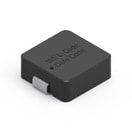 | SPECWE-LHMI SMT Power Inductor, –, – | Availability – | Status Activei| Production is active. Expected lifetime: >10 years. | Product seriesWE-LHMI SMT Power Inductor | – | – | – | Size4020 | Operating Temperature -40 °C up to +125 °C | – | – | – | Length4.45 mm | Width4.06 mm | Height1.8 mm | – | – | Inductance1 µH | – | – | – | DC Resistance27 mΩ | Self Resonant Frequency89 MHz | Performance Rated Current6.2 A | Saturation Current @ 30%12.5 A | DC Resistance22 mΩ | Operating Voltage120 V | MountSMT | Saturation Current @ 10%6.5 A | –Check availability | ||||||||||||||||||||||||||||||||||||||||||||||||||||||||||||||||||||||||||||||||||||||||||||||||||||||||||||||||||||||||||||||||||||||||||||||||||||||||||||||||||||||||||||||||||||||||||||||||||||||||||||||||||||||||||||||||||||||||||||||||||||||||||||||||||||||||||||||||||||||||||||||||||||||||||||||||||||||||||||||||||||||||||||||||||||||||||||||||||||||||||||||||||||||||||||||||||||||||||||||||||||||||||||||||||||||||||||||||||||||||||||||||||||||||||||||||||||||||||||||||||||||||||||||||||||||||||||||||||||||||||||||||||||||||||||||||||||||||||||||||||||||||||||||||||||||||||||||||||||||||||||||||||||||||||||||||||||||||||||||||||||||||||||||||||||||||||||||||||||||||||||||||||||||||||||||||||||||||||||||||||||||||||||||||||||||||||||||||||||||||||||||||||||||||||||||||||||||||||||||||||||||||||||||||||||||||||||||||||||||||||||||||||||||||||||||||||||||||||||||||||||||||||||||||||||||||||||||||||||||||||||||||||||||||||||||||||||||||||||||||||||||||
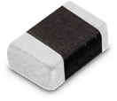 | SPECWE-PMCI Power Molded Chip Inductor, –, – | Availability – | Status Activei| Production is active. Expected lifetime: >10 years. | Product seriesWE-PMCI Power Molded Chip Inductor | – | – | – | Size252012 | Operating Temperature -40 °C up to +125 °C | – | – | – | Length2.5 mm | Width2 mm | Height1.2 mm | Pad Dimension0.6 mm | – | Inductance1.5 µH | Rated Current3.2 A | Saturation Current 11.35 A | Saturation Current 23.05 A | DC Resistance77 mΩ | Self Resonant Frequency70 MHz | Performance Rated Current3.2 A | Saturation Current @ 30%3.05 A | DC Resistance71 mΩ | – | MountSMT | Saturation Current @ 10%1.35 A | –Check availability | ||||||||||||||||||||||||||||||||||||||||||||||||||||||||||||||||||||||||||||||||||||||||||||||||||||||||||||||||||||||||||||||||||||||||||||||||||||||||||||||||||||||||||||||||||||||||||||||||||||||||||||||||||||||||||||||||||||||||||||||||||||||||||||||||||||||||||||||||||||||||||||||||||||||||||||||||||||||||||||||||||||||||||||||||||||||||||||||||||||||||||||||||||||||||||||||||||||||||||||||||||||||||||||||||||||||||||||||||||||||||||||||||||||||||||||||||||||||||||||||||||||||||||||||||||||||||||||||||||||||||||||||||||||||||||||||||||||||||||||||||||||||||||||||||||||||||||||||||||||||||||||||||||||||||||||||||||||||||||||||||||||||||||||||||||||||||||||||||||||||||||||||||||||||||||||||||||||||||||||||||||||||||||||||||||||||||||||||||||||||||||||||||||||||||||||||||||||||||||||||||||||||||||||||||||||||||||||||||||||||||||||||||||||||||||||||||||||||||||||||||||||||||||||||||||||||||||||||||||||||||||||||||||||||||||||||||||||||||||||||||||||||||
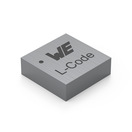 | SPECWE-MAPI SMT Power Inductor, –, – PCN pendingDue to a pending PCN there will be a new datasheet revision issued for this order code soon. Please find the actual as well based on valid PCN date the new revision datasheet below. If you have further questions please get in contact with our sales staff. | Availability – | Status Activei| Production is active. Expected lifetime: >10 years. | Product seriesWE-MAPI SMT Power Inductor | – | – | – | Size4020HT | Operating Temperature -55 °C up to +150 °C | – | – | – | Length4 mm | Width4 mm | Height2 mm | – | – | Inductance0.68 µH | Rated Current8.1 A | – | – | DC Resistance9.2 mΩ | Self Resonant Frequency67 MHz | Performance Rated Current11.7 A | Saturation Current @ 30%11.7 A | DC Resistance8 mΩ | Operating Voltage80 V | MountSMT | Saturation Current @ 10%5.45 A | –Check availability | ||||||||||||||||||||||||||||||||||||||||||||||||||||||||||||||||||||||||||||||||||||||||||||||||||||||||||||||||||||||||||||||||||||||||||||||||||||||||||||||||||||||||||||||||||||||||||||||||||||||||||||||||||||||||||||||||||||||||||||||||||||||||||||||||||||||||||||||||||||||||||||||||||||||||||||||||||||||||||||||||||||||||||||||||||||||||||||||||||||||||||||||||||||||||||||||||||||||||||||||||||||||||||||||||||||||||||||||||||||||||||||||||||||||||||||||||||||||||||||||||||||||||||||||||||||||||||||||||||||||||||||||||||||||||||||||||||||||||||||||||||||||||||||||||||||||||||||||||||||||||||||||||||||||||||||||||||||||||||||||||||||||||||||||||||||||||||||||||||||||||||||||||||||||||||||||||||||||||||||||||||||||||||||||||||||||||||||||||||||||||||||||||||||||||||||||||||||||||||||||||||||||||||||||||||||||||||||||||||||||||||||||||||||||||||||||||||||||||||||||||||||||||||||||||||||||||||||||||||||||||||||||||||||||||||||||||||||||||||||||||||||||||
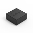 | SPECWE-XHMI SMT Power Inductor, –, – | Availability – | Status Activei| Production is active. Expected lifetime: >10 years. | Product seriesWE-XHMI SMT Power Inductor | – | – | – | Size4020 | Operating Temperature -40 °C up to +125 °C | – | – | – | Length4.3 mm | Width4.3 mm | Height2 mm | – | – | Inductance0.47 µH | – | – | – | DC Resistance6.69 mΩ | Self Resonant Frequency95 MHz | Performance Rated Current14.5 A | Saturation Current @ 30%12.8 A | DC Resistance5.25 mΩ | – | MountSMT | Saturation Current @ 10%5.6 A | –Check availability | ||||||||||||||||||||||||||||||||||||||||||||||||||||||||||||||||||||||||||||||||||||||||||||||||||||||||||||||||||||||||||||||||||||||||||||||||||||||||||||||||||||||||||||||||||||||||||||||||||||||||||||||||||||||||||||||||||||||||||||||||||||||||||||||||||||||||||||||||||||||||||||||||||||||||||||||||||||||||||||||||||||||||||||||||||||||||||||||||||||||||||||||||||||||||||||||||||||||||||||||||||||||||||||||||||||||||||||||||||||||||||||||||||||||||||||||||||||||||||||||||||||||||||||||||||||||||||||||||||||||||||||||||||||||||||||||||||||||||||||||||||||||||||||||||||||||||||||||||||||||||||||||||||||||||||||||||||||||||||||||||||||||||||||||||||||||||||||||||||||||||||||||||||||||||||||||||||||||||||||||||||||||||||||||||||||||||||||||||||||||||||||||||||||||||||||||||||||||||||||||||||||||||||||||||||||||||||||||||||||||||||||||||||||||||||||||||||||||||||||||||||||||||||||||||||||||||||||||||||||||||||||||||||||||||||||||||||||||||||||||||||||||||
| Expected Availability | Opening inventory | Quantity |
|---|---|---|
| Current Availability | – | – |