IC-Hersteller Texas Instruments
IC-Hersteller (107)
- Alle Hersteller
 Analog Devices
 Infineon Technologies
 Microchip
 Onsemi
 Renesas
 ROHM
ROHM STMicroelectronics
 Texas Instruments
- 3peak incorporated (35)
- Ablic (23)
- Acco Semiconductor (1)
- Advanced Power (4)
- Allegro Microsystems (100)
- Alpha & Omega Semiconductor (37)
- AnalogySemi (3)
- AnDAPT Inc (204)
- Anpec (13)
- AXElite (2)
- Backward (6)
- Bright Power Semiconductor (1)
- Broadcom (46)
- Cambridge GaN Devices (18)
- Chipanalog Micro (10)
- Cologne Chips (1)
- Convenient Power (1)
- Dialog Semiconductor (12)
- Diodes Incorporated (265)
- Divimath (8)
- Einnosemi (4)
- Elmos AG (1)
- EPC (146)
- e-Peas Semiconductors (1)
- Eta Solutions Co. Ltd. (9)
- GaN Systems (8)
- GaNPower (3)
- Giantec (1)
- Gosemicon (2)
- Gstek Wuxi (1)
- Helix Semiconductor (7)
- IKON (1)
- Indie Semiconductor (8)
- Innovision Semiconductor Inc (2)
- Intel (68)
- Inventchip Technology (3)
- ISSI (51)
- JoulWatt (20)
- KDPOF (3)
- Kinetic Technology (8)
- Lattice semiconductor Corporation (38)
- Littelfuse (1)
- Lumissil Microsystems (8)
- M3 Technology (M3Tek) (7)
- Macnica (22)
- Marvell Semiconductor (1)
- MaxLinear (181)
- Menlo Micro (1)
- MikroE (25)
- MindCet (2)
- Monolithic Power Systems (996)
- Navitas Semiconductor Inc (6)
- NewEdge Technologies, Inc. (1)
- Nexperia (268)
- Nisshinbo Micro Device Inc. (9)
- Nordic Semiconductor (1)
- Novosense Micro (1)
- NXP (346)
- O2 Micro International Ltd (10)
- On Bright (7)
- Panasonic (2)
- PN Junction Semiconductor (2)
- Power Integrations (117)
- Powermat (1)
- Pulsiv (19)
- Qorvo (99)
- Realsil SuRealsil(tek) Microelectronics (1)
- Richtek (297)
- Sanken Electric Co., Ltd. (16)
- Sckipio (6)
- Semtech (86)
- SG-Micro (62)
- SiFive (2)
- Silanna Semiconductor (9)
- Silergy Corporation (34)
- Silicon Laboratory Inc. (108)
- Silicontent Technology (59)
- Silvertel (59)
- Skycore Semiconductors (1)
- Skyworks (33)
- Southchip (29)
- Summit Wireless (1)
- Tagore Tech (7)
- Taiwan Semiconductor (1)
- TDK Corporation (1)
- Tempo Semiconductor (1)
- Torex (37)
- Toshiba (31)
- Transphorm (21)
- TransSIP (2)
- Union (21)
- uPI Semiconductor (2)
- Valens Semiconductor (31)
- VisIC (1)
- Wise Integration (3)
- Wolfspeed (23)
- Xilinx (22)
- XL Semiconductor (3)
- XYSemi (62)
Texas Instruments SN6505BDBVR | Demoboard FSI Adapter Board
Low-Noise 1-A Transformer Drivers for Isolated Power Supplies
Details
| Topologie | Gegentaktflusswandler |
| Schaltfrequenz | 160-420 kHz |
Beschreibung
Confidential c2000 ref design
Eigenschaften
- Push-pull driver for transformers
- Wide input voltage range: 2.25 V to 5.5 V
- High output drive: 1 A at 5 V supply
- Low RON 0.25 Ω max at 4.5 V supply
- Ultra-low EMI - Spread spectrum clocking
- Precision internal oscillator options: 160 kHz (SN6505A) and 420 kHz (SN6505B)
- Synchronization of multiple devices with external clock input
- Slew-rate control
- 1.7 A Current-limit
- Low shutdown current: <1 μA - Thermal shutdown
- Wide temperature range: –55°C to 125°C
- Small 6-Pin SOT23 (DBV) package
- Soft-start to reduce In-rush current
Typische Anwendungen
- Medical instruments
- Process control / Precision instruments
- Low-noise isolated USB supplies
- Isolated power supply for CAN, RS-485, RS-422, RS-232, SPI, I2C, low-power LAN / Telecom supplies / Radio supplies
- Distributed supplies
Weiterführende Informationen
Artikeldaten
Jetzt einloggen, um Verfügbarkeiten zu sehen und Verfügbarkeitsprognosen anzufragen. LOGIN
Artikel Nr. | Datenblatt | Simulation | Downloads | Status | Produktserie | Pins | Anwendung | PCB/Kabel/Panel | Modularity | Wire Section | λDom typ.(nm) | Emittierte Farbe | λPeak typ.(nm) | λPeak G typ.(nm) | λPeak Y typ.(nm) | IV typ.(mcd) | IV G typ.(mcd) | IV Y typ.(mcd) | VF typ.(V) | VF G typ.(V) | VF Y typ.(V) | Chiptechnologie | 2θ50% typ.(°) | Vin | VOut1(V) | IOut1(A) | Isolierungstyp | fswitch(kHz) | ∫Udt(Vµs) | NPRI : NSEC | L(µH) | VT(V (AC)) | L(mm) | B(mm) | H(mm) | Montageart | xPxC | Ausführung | Ports | Schirmung | Tab | EMI | LED | Anwendungssystem | IR(A) | Arbeitsspannung(V (AC)) | Verpackung | Interface typ | Gender | Betriebstemperatur | Z @ 100 MHz(Ω) | Zmax(Ω) | Testbedingung Zmax | IR 2(mA) | RDC max.(Ω) | Typ | MusterVerfügbarkeit & Muster | |||||||||||||||||||||||||||||||||||||||||||||||||||||||||||||||||||||||||||||||||||||||||||||||||||||||||||||||||||||||||||||||||||||||||||||||||||||||||||||||||||||||||||||||||||||||||||||||||||||||||||||||||||||||||||||||||||||||||||||||||||||||||||||||||||||||||||||||||||||||||||||||||||||||||||||||||||||||||||||||||||||||||||||||||||||||||||||||||||||||||||||||||||||||||||||||||||||||||||||||||||||||||||||||||||||||||||||||||||||||||||||||||||||||||||||||||||||||||||||||||||||||||||||||||||||||||||||||||||||||||||||||||||||||||||||||||||||||||||||||||||||||||||||||||||||||||||||||||||||||||||||||||||||||||||||||||||||||||||||||||||||||||||||||||||||||||||||||||||||||||||||||||||||||||||||||||||||||||||||||||||||||||||||||||||||||||||||||||||||||||||||||||||||||||||||||||||||||||||||||||||||||||||||||||||||||||||||||||||||||||||||||||||||||||||||||||||||||||||||||||||||||||||||||||||||||||||||||||||||||||||||||||||||||||||||
|---|---|---|---|---|---|---|---|---|---|---|---|---|---|---|---|---|---|---|---|---|---|---|---|---|---|---|---|---|---|---|---|---|---|---|---|---|---|---|---|---|---|---|---|---|---|---|---|---|---|---|---|---|---|---|---|---|---|---|---|---|---|---|---|---|---|---|---|---|---|---|---|---|---|---|---|---|---|---|---|---|---|---|---|---|---|---|---|---|---|---|---|---|---|---|---|---|---|---|---|---|---|---|---|---|---|---|---|---|---|---|---|---|---|---|---|---|---|---|---|---|---|---|---|---|---|---|---|---|---|---|---|---|---|---|---|---|---|---|---|---|---|---|---|---|---|---|---|---|---|---|---|---|---|---|---|---|---|---|---|---|---|---|---|---|---|---|---|---|---|---|---|---|---|---|---|---|---|---|---|---|---|---|---|---|---|---|---|---|---|---|---|---|---|---|---|---|---|---|---|---|---|---|---|---|---|---|---|---|---|---|---|---|---|---|---|---|---|---|---|---|---|---|---|---|---|---|---|---|---|---|---|---|---|---|---|---|---|---|---|---|---|---|---|---|---|---|---|---|---|---|---|---|---|---|---|---|---|---|---|---|---|---|---|---|---|---|---|---|---|---|---|---|---|---|---|---|---|---|---|---|---|---|---|---|---|---|---|---|---|---|---|---|---|---|---|---|---|---|---|---|---|---|---|---|---|---|---|---|---|---|---|---|---|---|---|---|---|---|---|---|---|---|---|---|---|---|---|---|---|---|---|---|---|---|---|---|---|---|---|---|---|---|---|---|---|---|---|---|---|---|---|---|---|---|---|---|---|---|---|---|---|---|---|---|---|---|---|---|---|---|---|---|---|---|---|---|---|---|---|---|---|---|---|---|---|---|---|---|---|---|---|---|---|---|---|---|---|---|---|---|---|---|---|---|---|---|---|---|---|---|---|---|---|---|---|---|---|---|---|---|---|---|---|---|---|---|---|---|---|---|---|---|---|---|---|---|---|---|---|---|---|---|---|---|---|---|---|---|---|---|---|---|---|---|---|---|---|---|---|---|---|---|---|---|---|---|---|---|---|---|---|---|---|---|---|---|---|---|---|---|---|---|---|---|---|---|---|---|---|---|---|---|---|---|---|---|---|---|---|---|---|---|---|---|---|---|---|---|---|---|---|---|---|---|---|---|---|---|---|---|---|---|---|---|---|---|---|---|---|---|---|---|---|---|---|---|---|---|---|---|---|---|---|---|---|---|---|---|---|---|---|---|---|---|---|---|---|---|---|---|---|---|---|---|---|---|---|---|---|---|---|---|---|---|---|---|---|---|---|---|---|---|---|---|---|---|---|---|---|---|---|---|---|---|---|---|---|---|---|---|---|---|---|---|---|---|---|---|---|---|---|---|---|---|---|---|---|---|---|---|---|---|---|---|---|---|---|---|---|---|---|---|---|---|---|---|---|---|---|---|---|---|---|---|---|---|---|---|---|---|---|---|---|---|---|---|---|---|---|---|---|---|---|---|---|---|---|---|---|---|---|---|---|---|---|---|---|---|---|---|---|---|---|---|---|---|---|---|---|---|---|---|---|---|---|---|---|---|---|---|---|---|---|---|---|---|---|---|---|---|---|---|---|---|---|---|---|---|---|---|---|---|---|---|---|---|---|---|---|---|---|---|---|---|---|---|---|---|---|---|---|---|---|---|---|---|---|---|---|---|---|---|---|---|---|---|---|---|---|---|---|---|---|---|---|---|---|---|---|---|---|---|---|---|---|---|---|---|---|---|---|---|---|---|---|---|---|---|---|---|---|---|---|---|---|---|---|---|---|---|---|---|---|---|---|---|---|---|---|---|---|---|---|---|---|---|---|---|---|---|---|---|---|---|---|---|---|---|---|---|---|---|---|---|---|---|---|---|---|---|---|---|---|---|---|---|---|---|---|---|---|---|---|---|---|---|---|---|---|---|---|---|---|---|---|---|---|---|---|---|---|---|---|---|---|---|---|---|---|---|---|---|---|---|---|---|---|---|---|---|---|---|---|---|---|---|---|---|---|---|---|---|---|---|---|---|---|---|---|---|---|---|---|---|---|---|---|---|---|---|---|---|---|---|---|---|---|---|---|---|---|---|---|---|---|---|---|---|---|---|---|---|---|---|---|---|---|---|---|---|---|---|---|---|---|---|---|---|---|---|---|---|---|---|---|---|---|---|---|---|---|---|---|---|---|---|---|---|---|---|---|---|---|---|---|---|---|---|---|---|---|---|---|---|---|---|---|---|
| Jetzt einloggen, um Verfügbarkeiten zu sehen und Verfügbarkeitsprognosen anzufragen. LOGIN | ||||||||||||||||||||||||||||||||||||||||||||||||||||||||||||||||||||||||||||||||||||||||||||||||||||||||||||||||||||||||||||||||||||||||||||||||||||||||||||||||||||||||||||||||||||||||||||||||||||||||||||||||||||||||||||||||||||||||||||||||||||||||||||||||||||||||||||||||||||||||||||||||||||||||||||||||||||||||||||||||||||||||||||||||||||||||||||||||||||||||||||||||||||||||||||||||||||||||||||||||||||||||||||||||||||||||||||||||||||||||||||||||||||||||||||||||||||||||||||||||||||||||||||||||||||||||||||||||||||||||||||||||||||||||||||||||||||||||||||||||||||||||||||||||||||||||||||||||||||||||||||||||||||||||||||||||||||||||||||||||||||||||||||||||||||||||||||||||||||||||||||||||||||||||||||||||||||||||||||||||||||||||||||||||||||||||||||||||||||||||||||||||||||||||||||||||||||||||||||||||||||||||||||||||||||||||||||||||||||||||||||||||||||||||||||||||||||||||||||||||||||||||||||||||||||||||||||||||||||||||||||||||||||||||||||||||||||||||||||||||||||||||||||||||||||||||||||||||||||||
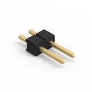 | SPECWR-PHD Stiftleisten - Einreihig, 2, – | Simulation– | Verfügbarkeit – | Status Aktivi| Produktion ist aktiv. Erwartete Lebenszeit: >10 Jahre. | ProduktserieWR-PHD Stiftleisten - Einreihig | Pins2 | – | – | – | – | – | – | – | – | – | – | – | – | – | – | – | – | – | – | – | – | – | – | – | – | – | – | Länge5.08 mm | – | – | MontageartTHT | – | – | – | – | – | – | – | – | Nennstrom3 A | Arbeitsspannung250 V (AC) | VerpackungBeutel | – | GenderStiftleiste | Betriebstemperatur -40 °C up to +105 °C | – | – | – | – | – | TypGerade | –Verfügbarkeit prüfen | |||||||||||||||||||||||||||||||||||||||||||||||||||||||||||||||||||||||||||||||||||||||||||||||||||||||||||||||||||||||||||||||||||||||||||||||||||||||||||||||||||||||||||||||||||||||||||||||||||||||||||||||||||||||||||||||||||||||||||||||||||||||||||||||||||||||||||||||||||||||||||||||||||||||||||||||||||||||||||||||||||||||||||||||||||||||||||||||||||||||||||||||||||||||||||||||||||||||||||||||||||||||||||||||||||||||||||||||||||||||||||||||||||||||||||||||||||||||||||||||||||||||||||||||||||||||||||||||||||||||||||||||||||||||||||||||||||||||||||||||||||||||||||||||||||||||||||||||||||||||||||||||||||||||||||||||||||||||||||||||||||||||||||||||||||||||||||||||||||||||||||||||||||||||||||||||||||||||||||||||||||||||||||||||||||||||||||||||||||||||||||||||||||||||||||||||||||||||||||||||||||||||||||||||||||||||||||||||||||||||||||||||||||||||||||||||||||||||||||||||||||||||||||||||||||||||||||||||||||||||||||||||||||||||||||||
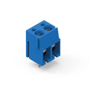 | SPECWR-TBL Series 101 - 5.00 mm Horizontal Entry Modular, 2, Kabelschutzprinzip | Simulation– | Verfügbarkeit – | Downloads7 Dateien | Status Aktivi| Produktion ist aktiv. Erwartete Lebenszeit: >10 Jahre. | Pins2 | AnwendungKabelschutzprinzip | PCB/Kabel/PanelPCB | ModularityJa | Wire Section 26 to 14 (AWG) 0.5 to 2.5 (mm²) | – | – | – | – | – | – | – | – | – | – | – | – | – | – | – | – | – | – | – | – | – | – | Länge10 mm | – | Höhe12.6 mm | MontageartTHT | – | – | – | – | – | – | – | – | Nennstrom16 A | Arbeitsspannung250 V (AC) | VerpackungKarton | – | – | Betriebstemperatur -40 °C up to +105 °C | – | – | – | – | – | TypHorizontal | –Verfügbarkeit prüfen | |||||||||||||||||||||||||||||||||||||||||||||||||||||||||||||||||||||||||||||||||||||||||||||||||||||||||||||||||||||||||||||||||||||||||||||||||||||||||||||||||||||||||||||||||||||||||||||||||||||||||||||||||||||||||||||||||||||||||||||||||||||||||||||||||||||||||||||||||||||||||||||||||||||||||||||||||||||||||||||||||||||||||||||||||||||||||||||||||||||||||||||||||||||||||||||||||||||||||||||||||||||||||||||||||||||||||||||||||||||||||||||||||||||||||||||||||||||||||||||||||||||||||||||||||||||||||||||||||||||||||||||||||||||||||||||||||||||||||||||||||||||||||||||||||||||||||||||||||||||||||||||||||||||||||||||||||||||||||||||||||||||||||||||||||||||||||||||||||||||||||||||||||||||||||||||||||||||||||||||||||||||||||||||||||||||||||||||||||||||||||||||||||||||||||||||||||||||||||||||||||||||||||||||||||||||||||||||||||||||||||||||||||||||||||||||||||||||||||||||||||||||||||||||||||||||||||||||||||||||||||||||||||||||||||||||
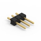 | SPECWR-PHD Stiftleisten - Einreihig, 3, – | Simulation– | Verfügbarkeit – | Status Aktivi| Produktion ist aktiv. Erwartete Lebenszeit: >10 Jahre. | ProduktserieWR-PHD Stiftleisten - Einreihig | Pins3 | – | – | – | – | – | – | – | – | – | – | – | – | – | – | – | – | – | – | – | – | – | – | – | – | – | – | Länge7.62 mm | – | – | MontageartTHT | – | – | – | – | – | – | – | – | Nennstrom3 A | Arbeitsspannung250 V (AC) | VerpackungBeutel | – | GenderStiftleiste | Betriebstemperatur -40 °C up to +105 °C | – | – | – | – | – | TypGerade | –Verfügbarkeit prüfen | |||||||||||||||||||||||||||||||||||||||||||||||||||||||||||||||||||||||||||||||||||||||||||||||||||||||||||||||||||||||||||||||||||||||||||||||||||||||||||||||||||||||||||||||||||||||||||||||||||||||||||||||||||||||||||||||||||||||||||||||||||||||||||||||||||||||||||||||||||||||||||||||||||||||||||||||||||||||||||||||||||||||||||||||||||||||||||||||||||||||||||||||||||||||||||||||||||||||||||||||||||||||||||||||||||||||||||||||||||||||||||||||||||||||||||||||||||||||||||||||||||||||||||||||||||||||||||||||||||||||||||||||||||||||||||||||||||||||||||||||||||||||||||||||||||||||||||||||||||||||||||||||||||||||||||||||||||||||||||||||||||||||||||||||||||||||||||||||||||||||||||||||||||||||||||||||||||||||||||||||||||||||||||||||||||||||||||||||||||||||||||||||||||||||||||||||||||||||||||||||||||||||||||||||||||||||||||||||||||||||||||||||||||||||||||||||||||||||||||||||||||||||||||||||||||||||||||||||||||||||||||||||||||||||||||||
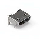 | SPECWR-USB Mini/Micro Steckverbinder, 5, Micro USB 2.0 | Simulation– | Verfügbarkeit – | Status Aktivi| Produktion ist aktiv. Erwartete Lebenszeit: >10 Jahre. | ProduktserieWR-USB Mini/Micro Steckverbinder | Pins5 | AnwendungMicro USB 2.0 | – | – | – | – | – | – | – | – | – | – | – | – | – | – | – | – | – | – | – | – | – | – | – | – | – | – | – | – | MontageartSMT | – | AusführungMit Pegs- High Current | – | – | – | – | – | – | Nennstrom3 A | Arbeitsspannung30 V (AC) | VerpackungTape and Reel | Interface typType B | GenderBuchse | Betriebstemperatur -40 °C up to +85 °C | – | – | – | – | – | TypHorizontal | –Verfügbarkeit prüfen | |||||||||||||||||||||||||||||||||||||||||||||||||||||||||||||||||||||||||||||||||||||||||||||||||||||||||||||||||||||||||||||||||||||||||||||||||||||||||||||||||||||||||||||||||||||||||||||||||||||||||||||||||||||||||||||||||||||||||||||||||||||||||||||||||||||||||||||||||||||||||||||||||||||||||||||||||||||||||||||||||||||||||||||||||||||||||||||||||||||||||||||||||||||||||||||||||||||||||||||||||||||||||||||||||||||||||||||||||||||||||||||||||||||||||||||||||||||||||||||||||||||||||||||||||||||||||||||||||||||||||||||||||||||||||||||||||||||||||||||||||||||||||||||||||||||||||||||||||||||||||||||||||||||||||||||||||||||||||||||||||||||||||||||||||||||||||||||||||||||||||||||||||||||||||||||||||||||||||||||||||||||||||||||||||||||||||||||||||||||||||||||||||||||||||||||||||||||||||||||||||||||||||||||||||||||||||||||||||||||||||||||||||||||||||||||||||||||||||||||||||||||||||||||||||||||||||||||||||||||||||||||||||||||||||||||
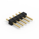 | SPECWR-PHD Stiftleisten - Einreihig, 5, – | Simulation– | Verfügbarkeit – | Status Aktivi| Produktion ist aktiv. Erwartete Lebenszeit: >10 Jahre. | ProduktserieWR-PHD Stiftleisten - Einreihig | Pins5 | – | – | – | – | – | – | – | – | – | – | – | – | – | – | – | – | – | – | – | – | – | – | – | – | – | – | Länge12.7 mm | – | – | MontageartTHT | – | – | – | – | – | – | – | – | Nennstrom3 A | Arbeitsspannung250 V (AC) | VerpackungBeutel | – | GenderStiftleiste | Betriebstemperatur -40 °C up to +105 °C | – | – | – | – | – | TypGerade | –Verfügbarkeit prüfen | |||||||||||||||||||||||||||||||||||||||||||||||||||||||||||||||||||||||||||||||||||||||||||||||||||||||||||||||||||||||||||||||||||||||||||||||||||||||||||||||||||||||||||||||||||||||||||||||||||||||||||||||||||||||||||||||||||||||||||||||||||||||||||||||||||||||||||||||||||||||||||||||||||||||||||||||||||||||||||||||||||||||||||||||||||||||||||||||||||||||||||||||||||||||||||||||||||||||||||||||||||||||||||||||||||||||||||||||||||||||||||||||||||||||||||||||||||||||||||||||||||||||||||||||||||||||||||||||||||||||||||||||||||||||||||||||||||||||||||||||||||||||||||||||||||||||||||||||||||||||||||||||||||||||||||||||||||||||||||||||||||||||||||||||||||||||||||||||||||||||||||||||||||||||||||||||||||||||||||||||||||||||||||||||||||||||||||||||||||||||||||||||||||||||||||||||||||||||||||||||||||||||||||||||||||||||||||||||||||||||||||||||||||||||||||||||||||||||||||||||||||||||||||||||||||||||||||||||||||||||||||||||||||||||||||||
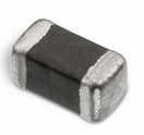 | SPECWE-CBF SMT-Ferrit, –, – | Verfügbarkeit – | Status Aktivi| Produktion ist aktiv. Erwartete Lebenszeit: >10 Jahre. | ProduktserieWE-CBF SMT-Ferrit | – | – | – | – | – | – | – | – | – | – | – | – | – | – | – | – | – | – | – | – | – | – | – | – | – | – | – | Länge1.6 mm | Breite0.8 mm | Höhe0.8 mm | MontageartSMT | – | – | – | – | – | – | – | – | Nennstrom0.5 A | – | – | – | – | Betriebstemperatur -55 °C up to +125 °C | Impedanz @ 100 MHz100 Ω | Maximale Impedanz125 Ω | Maximale Impedanz450 MHz | Nennstrom 21650 mA | Gleichstromwiderstand0.15 Ω | TypBreitband | –Verfügbarkeit prüfen | ||||||||||||||||||||||||||||||||||||||||||||||||||||||||||||||||||||||||||||||||||||||||||||||||||||||||||||||||||||||||||||||||||||||||||||||||||||||||||||||||||||||||||||||||||||||||||||||||||||||||||||||||||||||||||||||||||||||||||||||||||||||||||||||||||||||||||||||||||||||||||||||||||||||||||||||||||||||||||||||||||||||||||||||||||||||||||||||||||||||||||||||||||||||||||||||||||||||||||||||||||||||||||||||||||||||||||||||||||||||||||||||||||||||||||||||||||||||||||||||||||||||||||||||||||||||||||||||||||||||||||||||||||||||||||||||||||||||||||||||||||||||||||||||||||||||||||||||||||||||||||||||||||||||||||||||||||||||||||||||||||||||||||||||||||||||||||||||||||||||||||||||||||||||||||||||||||||||||||||||||||||||||||||||||||||||||||||||||||||||||||||||||||||||||||||||||||||||||||||||||||||||||||||||||||||||||||||||||||||||||||||||||||||||||||||||||||||||||||||||||||||||||||||||||||||||||||||||||||||||||||||||||||||||||||||||
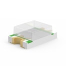 | SPECWL-SMCW SMT Mono-color Chip LED Waterclear, –, – | Verfügbarkeit – | Status Aktivi| Produktion ist aktiv. Erwartete Lebenszeit: >10 Jahre. | ProduktserieWL-SMCW SMT Mono-color Chip LED Waterclear | – | – | – | – | – | dominante Wellenlänge [typ.]630 nm | Emittierte FarbeSuperrot | Spitzen-Wellenlänge [typ.]645 nm | – | – | Lichtstärke [typ.]60 mcd | – | – | Durchlassspannung [typ.]1.9 V | – | – | ChiptechnologieAlInGaP | Abstrahlwinkel Phi 0° [typ.]140 ° | – | – | – | – | – | – | – | – | – | Länge2 mm | Breite1.25 mm | Höhe0.7 mm | MontageartSMT | – | – | – | – | – | – | – | – | – | – | VerpackungTape and Reel | – | – | Betriebstemperatur -40 °C up to +85 °C | – | – | – | – | – | – | –Verfügbarkeit prüfen | ||||||||||||||||||||||||||||||||||||||||||||||||||||||||||||||||||||||||||||||||||||||||||||||||||||||||||||||||||||||||||||||||||||||||||||||||||||||||||||||||||||||||||||||||||||||||||||||||||||||||||||||||||||||||||||||||||||||||||||||||||||||||||||||||||||||||||||||||||||||||||||||||||||||||||||||||||||||||||||||||||||||||||||||||||||||||||||||||||||||||||||||||||||||||||||||||||||||||||||||||||||||||||||||||||||||||||||||||||||||||||||||||||||||||||||||||||||||||||||||||||||||||||||||||||||||||||||||||||||||||||||||||||||||||||||||||||||||||||||||||||||||||||||||||||||||||||||||||||||||||||||||||||||||||||||||||||||||||||||||||||||||||||||||||||||||||||||||||||||||||||||||||||||||||||||||||||||||||||||||||||||||||||||||||||||||||||||||||||||||||||||||||||||||||||||||||||||||||||||||||||||||||||||||||||||||||||||||||||||||||||||||||||||||||||||||||||||||||||||||||||||||||||||||||||||||||||||||||||||||||||||||||||||||||||||||
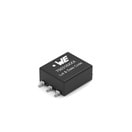 | SPECWE-PPTI Push-Pull Transformers, –, – | Simulation– | Verfügbarkeit – | Status Aktivi| Produktion ist aktiv. Erwartete Lebenszeit: >10 Jahre. | ProduktserieWE-PPTI Push-Pull Transformers | – | – | – | – | – | – | – | – | – | – | – | – | – | – | – | – | – | – | Input Voltage 3.3 V (DC) | Ausgangsspannung 13.3 V | Ausgangsstrom 10.8 A | IsolierungstypFunktional | Switching Frequency 400 - 700 | Spannung-µSekunde13 Vµs | Übersetzungsverhältnis1:1.75 | Induktivität86 µH | Prüfspannung2500 V (AC) | Länge8.3 mm | Breite12.6 mm | Höhe4.1 mm | MontageartSMT | – | – | – | – | – | – | – | – | – | – | VerpackungTape and Reel | – | – | Betriebstemperatur -40 °C up to +125 °C | – | – | – | – | – | – | –Verfügbarkeit prüfen | |||||||||||||||||||||||||||||||||||||||||||||||||||||||||||||||||||||||||||||||||||||||||||||||||||||||||||||||||||||||||||||||||||||||||||||||||||||||||||||||||||||||||||||||||||||||||||||||||||||||||||||||||||||||||||||||||||||||||||||||||||||||||||||||||||||||||||||||||||||||||||||||||||||||||||||||||||||||||||||||||||||||||||||||||||||||||||||||||||||||||||||||||||||||||||||||||||||||||||||||||||||||||||||||||||||||||||||||||||||||||||||||||||||||||||||||||||||||||||||||||||||||||||||||||||||||||||||||||||||||||||||||||||||||||||||||||||||||||||||||||||||||||||||||||||||||||||||||||||||||||||||||||||||||||||||||||||||||||||||||||||||||||||||||||||||||||||||||||||||||||||||||||||||||||||||||||||||||||||||||||||||||||||||||||||||||||||||||||||||||||||||||||||||||||||||||||||||||||||||||||||||||||||||||||||||||||||||||||||||||||||||||||||||||||||||||||||||||||||||||||||||||||||||||||||||||||||||||||||||||||||||||||||||||||||||
 | SPECWR-MJ Cat 3 Modular Jacks – THT, –, – | Simulation– | Verfügbarkeit – | Status Aktivi| Produktion ist aktiv. Erwartete Lebenszeit: >10 Jahre. | ProduktserieWR-MJ Cat 3 Modular Jacks – THT | – | – | – | – | – | – | – | – | Spitzen-Wellenlänge (Grün) [typ.]570 nm | Spitzen-Wellenlänge (Gelb) [typ.]590 nm | – | Lichtstärke (Grün) [typ.]13 mcd | Lichtstärke (Gelb) [typ.]8 mcd | – | Durchlassspannung (Grün) [typ.]2.3 V | Durchlassspannung (Gelb) [typ.]2.3 V | – | Abstrahlwinkel Phi 0° [typ.]140 ° | – | – | – | – | – | – | – | – | – | – | – | – | MontageartTHT | Anzahl der Pins (xPxC)8P8C | AusführungLow Profile | Ports1x1 | Schirmunggeschirmt | Tab PositionOben | EMI FingerJa | LED (Links-Rechts)gelb-grün | AnwendungssystemCAT 3 | Nennstrom1.5 A | Arbeitsspannung125 V (AC) | VerpackungTape and Reel | – | – | Betriebstemperatur -40 °C up to +85 °C | – | – | – | – | – | TypHorizontal | –Verfügbarkeit prüfen | |||||||||||||||||||||||||||||||||||||||||||||||||||||||||||||||||||||||||||||||||||||||||||||||||||||||||||||||||||||||||||||||||||||||||||||||||||||||||||||||||||||||||||||||||||||||||||||||||||||||||||||||||||||||||||||||||||||||||||||||||||||||||||||||||||||||||||||||||||||||||||||||||||||||||||||||||||||||||||||||||||||||||||||||||||||||||||||||||||||||||||||||||||||||||||||||||||||||||||||||||||||||||||||||||||||||||||||||||||||||||||||||||||||||||||||||||||||||||||||||||||||||||||||||||||||||||||||||||||||||||||||||||||||||||||||||||||||||||||||||||||||||||||||||||||||||||||||||||||||||||||||||||||||||||||||||||||||||||||||||||||||||||||||||||||||||||||||||||||||||||||||||||||||||||||||||||||||||||||||||||||||||||||||||||||||||||||||||||||||||||||||||||||||||||||||||||||||||||||||||||||||||||||||||||||||||||||||||||||||||||||||||||||||||||||||||||||||||||||||||||||||||||||||||||||||||||||||||||||||||||||||||||||||||||||||
Verfügbarkeitsprognose
WE Artikelnummer VerpackungseinheitenWiederbeschaffungszeit
––– Wochen
| Erwartete Verfügbarkeit | Eingehender Bestand | Menge |
|---|---|---|
| Aktuelle Verfügbarkeit | – | – |
Für diese Mengenanfrage gibt es keine Prognose.
Es passt einfach nicht?Nehmen Sie Kontakt mit uns auf, damit wir unsere Lager weltweit prüfen und ihre Bestellung priorisieren können.Kontaktieren sie uns