Würth Elektronik has extended its capacitor portfolio. You will find an overview of our current technologies available ex stock in the graph. More details (e.g. series, characteristics, features, applications, etc.) about each product family can be found in the flyer or for example below. In our flyer you will also find information about our services.
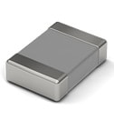
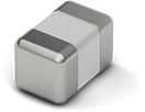
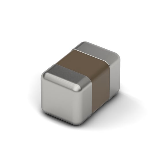
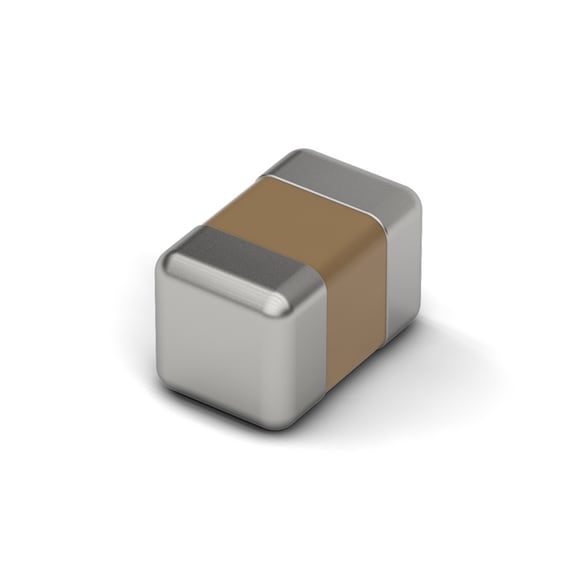
Würth Elektronik offers a large portfolio of MLCC sizes up to 2220. While downsizing might be the right choice for some applications, others require larger sizes of MLCCs for keeping the required electrical performance, volumetric capacitance and DC bias behavior. Long term availability ex stock. High quality samples free of charge make Würth Elektronik the perfect long-term partner for your MLCC demands.
Large portfolio from 0201 up to 2220
Long term availability
Detailed application-relevant measurement data available
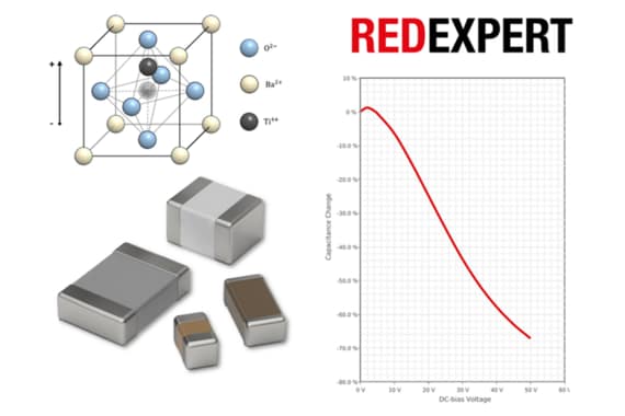
Sophisticated simulations available in online platform REDEXPERT
What needs to be considered while selecting MLCCs?
Class 1 (e.g.: NP0 = C0G)
In class 1, the material used is titanium oxide. There are smaller capacitance values in this class, which have low dependencies and have smaller tolerances. These types are used for all applications that require a fixed and stable capacitance value (e.g. real-time clock RTC).
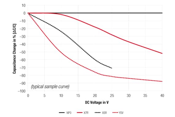
Class 2 (e.g.: X7R, X5R, Y5V)
The material barium titanate is used for class 2. Features of this class are larger capacitance values, which have strong environment and application dependencies. This is due to the ferroelectric property of barum titanate and is reflected in capacitance dependencies:
Capacity vs. Temperature
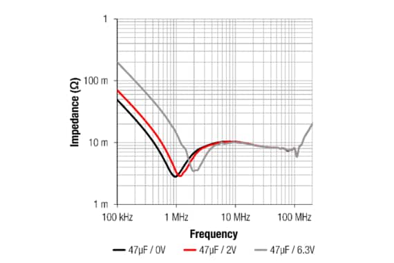
DC bias (dependence of the capacity on the applied DC voltage)
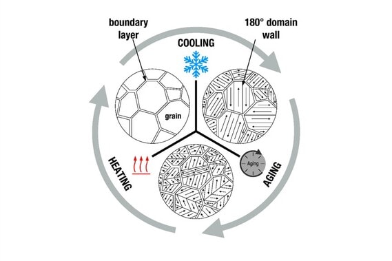
Aging behaviour
In addition, this material structure has piezoelectricity, which can also lead to microphonics.
How much capacitance do you really get? Class 2 examples
The capacitance value changes in an active application. Check the manufacturer's information to evaluate the occurring effects and the resulting capacitance. The following examples give an insight into the calculation of the best and worst case of the capacitance change of class 2 MLCCs.
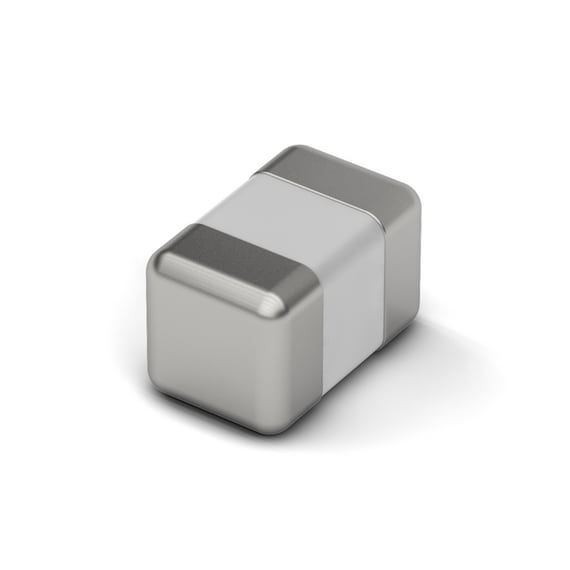
Construction
Internal structure
Construction
Internal structure
The ceramic is sintered from granules of paraelectric or ferroelectric base materials. It forms the dielectric of the capacitor. The electrodes of the capacitor are printed on it using a screen printing process. This results in a layer of ceramic and electrode. For ceramic multilayer capacitors, several of these layers are arranged offset one on top of the other. The termination surfaces are electrically conductively connected to the electrodes.
Example applications
Embedded board
Drilling machine
Power Supply
EV Charger
Antenna matching
Measurements
Redexpert
Measurements
Redexpert
With the help of REDEXPERT you will find the right capacitor based on your technical requirements. The tool supports, for example, with measured values for capacitance, impedance, ESR and dissipation factor (DF). The ability to compare individual components with each other in terms of measured values enables convenient component selection.
Support Note SN011: Why does the capacity of MLCCs change?
Why does the capacity of MLCCs change? Ambient temperature, structural changes or component tolerances play an important role. This document provides an overview of the most important factors, how these can be reduced by using a different material or external influences
Application Note ANP062: LC-Filterdesign mit MLCCs: Warum die angelegte Spannung am Filter zu beachten ist
How does the DC voltage influence the behavior of an capacitor, and hence the filter design? Simulated and measured results are compared with different components and materials.
ANP109: Impedance Spectra of Different Capacitor Technologies
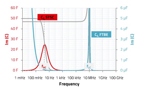
Impedance and capacitance spectra (or scattering parameters) are common representations of frequency dependent electrical properties of capacitors. The interpretation of such spectra provides a wide range of electrochemical, physical and technical relevant information. Those need to be separated from the ever-present measurement artifacts as well as parasitic effects.
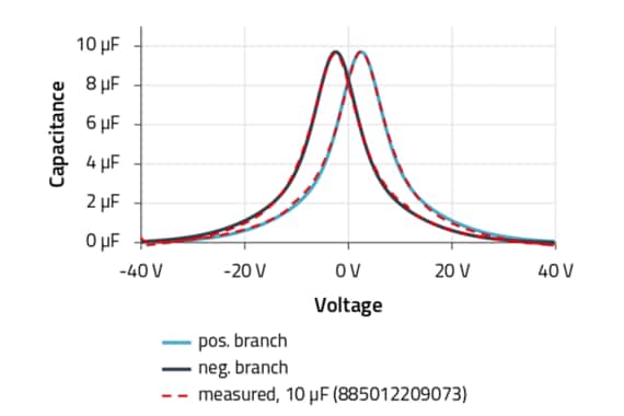
Application Note ANP114 Voltage and Frequency Dependence of Ferroelectric Class 2 Multilayer Ceramic Capacitors
After introducing ferroelectricity, a mathematical model for the capacitance-voltage behavior of multilayer ceramic capacitors (MLCCs) is derived from a dipole polarization model. The parameters of the model are reduced to two fitting parameters.
Multilayer Cermaic Capacitors are separated into different classes. What are the differences between Class 1 and Class 2 MLCC’s and what are the key parameters? We provide a short overview.
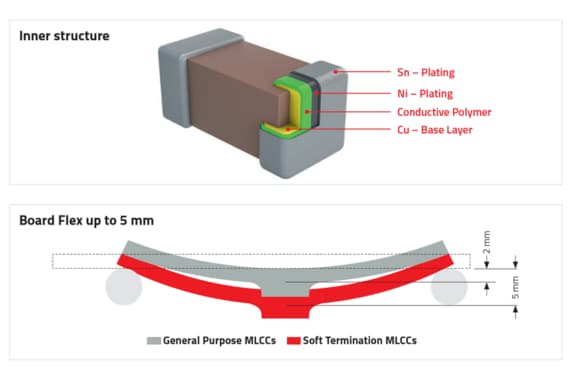
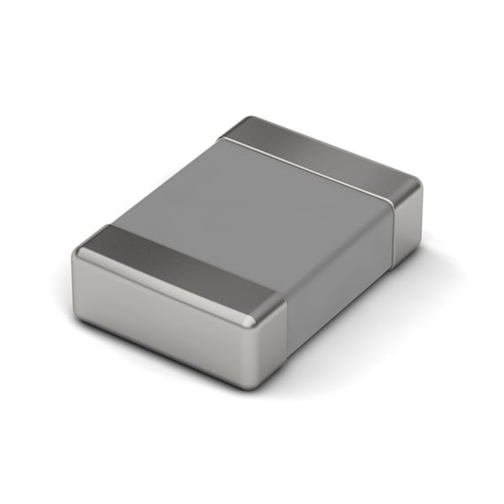
In the MLCCs - Soft Termination (WCAP-CSST) series, a layer of conductive polymer is used between the electrodes and the terminal surfaces. The polymer can compensate for certain mechanical deformations and therefore reduce the probability of fractures. This is illustrated by a bending test described in the data sheet.
Application Note ANP123 Long- and Short-Term Voltage Dependence of Ferroelectric Class 2 MLCCs
For the design-in process, it has become a common procedure to employ simulation software such as SPICE. The developer may load files for multilayer ceramic capacitors (MLCCs) into the software to simulate the influence of the voltage and frequency behavior of the MLCCs on the circuit. To make this simulation computationally efficient, it is necessary to implement elegant mathematical models for the MLCCs.
For most parts you can find the detailed information about packaging in the datasheet: If you cannot find them, please get in contact with Würth Elektronik. E.g. you can use the chat on the website.
Example: Page 3 of WCAP-CSRF component datasheet.
You can find the certifications in the datasheet, page 2.
In the case of X/Y safety capacitors, certification information can be found in PDF format in the online platform REDEXPERT.
These links are shown at the right end of the table, under the column “Certificates”.
We provide the document with all the values on our homepage.
You can also download the document by searching for “FIT” or “MTBF” in our download center.
This document reveals the FIT (Failures in time) and MTBF (Mean time between failures) values that can be calculated for each series based on the electrical stress (voltage applied in the case of capacitors) and the temperature applied according to calculation models of Telcordia SR-332 Issue 3.
Please refer to the table of contents at the beginning of the document to find the values for capacitors.
Figure 1: example of DC-drifts in REDEXPERT
Class 2 ceramic capacitors (X7R, X5R, X6S, ...) show a strong dependence of their capacitance in relation to the applied voltage. This effect varies depending on the component, with capacitance changes of over 80% possible in some cases.
We therefore measure each individual part number and display the results in REDEXPERT. The measured capacitance can be read off in a diagram below the components for each component.
A great option is that you can set the application voltage in the diagram. A new column then appears in the table above. This column can then be used to sort by capacitance, for example, so that the component with the highest capacitance under your conditions is selected.
As the components are made of the brittle material ceramic, mechanical stress can lead to cracks in these components. These cracks are often invisible.
To reduce the risk of cracks, we recommend the following:
Place the MLCCs as far away as possible from the edges of the PCB or other sources of mechanical stress.
If not otherwise possible, place the MLCCs with the long side of the component parallel to the PCB edge.
Use special soft termination MLCCs (series: WCAP-CSST). These components have a highly conductive polymer layer in the termination layer that can compensate for certain mechanical loads.
The bending test for soft termination MLCCs (WCAP-CSST) is specified in the data sheet as follows:


")