IC-Hersteller (105)
- Alle Hersteller
 Analog Devices
 Infineon Technologies
 Microchip
 Onsemi
 Renesas
 ROHM
ROHM STMicroelectronics
 Texas Instruments
- 3peak incorporated (35)
- Ablic (23)
- Acco Semiconductor (1)
- Advanced Power (4)
- Allegro Microsystems (100)
- Alpha & Omega Semiconductor (37)
- AnalogySemi (3)
- AnDAPT Inc (204)
- Anpec (13)
- AXElite (2)
- Backward (6)
- Bright Power Semiconductor (1)
- Broadcom (46)
- Cambridge GaN Devices (18)
- Chipanalog Micro (10)
- Cologne Chips (1)
- Convenient Power (1)
- Dialog Semiconductor (12)
- Diodes Incorporated (257)
- Divimath (8)
- Elmos AG (1)
- EPC (146)
- e-Peas Semiconductors (1)
- Eta Solutions Co. Ltd. (9)
- GaN Systems (8)
- GaNPower (3)
- Giantec (1)
- Gstek Wuxi (1)
- Helix Semiconductor (7)
- IKON (1)
- Indie Semiconductor (8)
- Innovision Semiconductor Inc (2)
- Intel (68)
- Inventchip Technology (3)
- ISSI (51)
- JoulWatt (20)
- KDPOF (3)
- Kinetic Technology (8)
- Lattice semiconductor Corporation (38)
- Littelfuse (1)
- Lumissil Microsystems (8)
- M3 Technology (M3Tek) (7)
- Macnica (22)
- Marvell Semiconductor (1)
- MaxLinear (181)
- Menlo Micro (1)
- MikroE (25)
- MindCet (2)
- Monolithic Power Systems (982)
- Navitas Semiconductor Inc (6)
- NewEdge Technologies, Inc. (1)
- Nexperia (268)
- Nisshinbo Micro Device Inc. (10)
- Nordic Semiconductor (1)
- Novosense Micro (1)
- NXP (341)
- O2 Micro International Ltd (10)
- On Bright (7)
- Panasonic (2)
- PN Junction Semiconductor (2)
- Power Integrations (117)
- Powermat (1)
- Pulsiv (19)
- Qorvo (99)
- Realsil SuRealsil(tek) Microelectronics (1)
- Richtek (297)
- Sanken Electric Co., Ltd. (16)
- Sckipio (6)
- Semtech (86)
- SG-Micro (58)
- SiFive (2)
- Silanna Semiconductor (9)
- Silergy Corporation (34)
- Silicon Laboratory Inc. (108)
- Silicontent Technology (59)
- Silvertel (59)
- Skycore Semiconductors (1)
- Skyworks (33)
- Southchip (18)
- Summit Wireless (1)
- Tagore Tech (7)
- Taiwan Semiconductor (1)
- TDK Corporation (1)
- Tempo Semiconductor (1)
- Torex (37)
- Toshiba (27)
- Transphorm (21)
- TransSIP (2)
- Union (21)
- uPI Semiconductor (2)
- Valens Semiconductor (31)
- VisIC (1)
- Wise Integration (3)
- Wolfspeed (23)
- Xilinx (22)
- XL Semiconductor (3)
- XYSemi (62)
Details
| Topologie | Sonstige Topologie |
| IC-Revision | 1.0 |
Beschreibung
The STEVAL-DPSG474Q is a control board dedicated to digital power applications.It can control the power stage of converters requiring high pin counting (PFC, DC-DC, DCAC), or can be used to control the dual stage conversion (PFC+DCDC).The STEVAL-DPSG474Q consists of a platform based on the STM32G474QE microcontroller from the STM32G4 family.The STM32G474QE microcontroller includes the high-performance Arm® Cortex®-M4 32-bit RISC core operating at up to 170 MHz frequency, a floating-point unit (FPU), a full set of DSP (digital signal processing) instructions, and high-speed embedded memories (512 Kbytes of flash memory and 128 Kbytes of SRAM).The device embeds peripherals that allow mathematical/arithmetic function acceleration (CORDIC for trigonometric functions and FMAC unit for filter functions).The MCU offers: five fast 12-bit ADCs (5 Msps), seven ultrafast comparators, six operational amplifiers, seven DAC channels (three external and four internal), a low-power RTC, 32-bit timers, three timers dedicated to motor control, seven general-purpose 16-bit timers, one 16-bit low-power timer, and the high-resolution timer (HRTIM) with 184 ps resolution, specifically designed to drive power conversion systems.The main connector embeds two sections for separate analog and digital behavior, with 32 pins and 68 pins respectively. It provides all the PWM control signals, sensing networks, and protection features needed for a wide range of digital power supply applications.A full pin-count STM32G474QE solution, in addition to the sophisticated embedded hardware accelerator, and powerful Arm® core, enables handling complex digital power converters like multilevel and multistage structures. Several connectors also allow extending the capability of this platform in terms of I/O, communication, telemetry, debugging, and control plus protection features.Full integration into the STM32Cube environment and digital power ST firmware package support allow implementing and deploying digital power converter control with a dedicated architecture and control features, to evaluate several turnkey control structures. Additional embedded debugging features such as LEDs and analog, digital test points maximize the design capability for the user.
Eigenschaften
Control board for power converters: SMPS, PFC, DC-DC and DC-AC convertersSTM32G474QET6 Arm Cortex®-M4 core-based microcontroller, featuring 512 Kbytes of flash memory and 128 Kbytes of SRAM, in LQFP128 packageLDO embedded for 5 V supplyBoard connectors32-pin digital and 68-pin analog main connectorUSB micro 5 V onlySTDC14 STLINK programming and debug connectorAnalog waveform test pointIsolated serial COMExpansion board DIG/AN connectorsESD protection and filter for MCU pin connectionsAnalog and digital pins test pointsExpansion connectorsSWIM–UART–I2C communication protocol connector14-pin analog and digital connectors3 user LEDs (status–error–fault)1 bicolor LED for full debuggingReset buttonSupport of a wide choice of integrated development environments (IDEs)IAR™, Keil®, and STM32CubeIDEEcosystem compatibilitySTM32Cube environmentDigital power STMicroelectronics firmware package
Typische Anwendungen
- Power supplies and converters
Weiterführende Informationen
Artikeldaten
Artikel Nr. | Datenblatt | Simulation | Downloads | Status | Produktserie | λDom typ.(nm) | Emittierte Farbe | λPeak typ.(nm) | λPeak R typ.(nm) | λPeak V typ.(nm) | λDom R typ.(nm) | λDom V typ.(nm) | IV typ.(mcd) | IV R typ.(mcd) | IV V typ.(mcd) | VF typ.(V) | VF R typ.(V) | VF V typ.(V) | Chiptechnologie | 2θ50% typ.(°) | C | Tol. C | VR(V (DC)) | Bauform | Betriebstemperatur | Q | DF(%) | RISO | Keramiktyp | L(mm) | B(mm) | H(mm) | Fl(mm) | Verpackung | Anwendung | Interface typ | Ausführung | Gender | Pins | Montageart | IR(mA) | Arbeitsspannung(V (AC)) | Farbe | Z @ 100 MHz(Ω) | Zmax(Ω) | Testbedingung Zmax | IR 2(mA) | RDC max.(Ω) | Typ | MusterVerfügbarkeit & Muster | ||||||||||||||||||||||||||||||||||||||||||||||||||||||||||||||||||||||||||||||||||||||||||||||||||||||||||||||||||||||||||||||||||||||||||||||||||||||||||||||||||||||||||||||||||||||||||||||||||||||||||||||||||||||||||||||||||||||||||||||||||||||||||||||||||||||||||||||||||||||||||||||||||||||||||||||||||||||||||||||||||||||||||||||||||||||||||||||||||||||||||||||||||||||||||||||||||||||||||||||||||||||||||||||||||||||||||||||||||||||||||||||||||||||||||||||||||||||||||||||||||||||||||||||||||||||||||||||||||||||||||||||||||||||||||||||||||||||||||||||||||||||||||||||||||||||||||||||||||||||||||||||||||||||||||||||||||||||||||||||||||||||||||||||||||||||||||||||||||||||||||||||||||||||||||||||||||||||||||||||||||||||||||||||||||||||||||||||||||||||||||||||||||||||||||||||||||||||||||||||||||||||||||||||||||||||||||||||||||||||||||||||||||||||||||||||||||||||||||||||||||||||||||||||||||||||||||||||||||||||||||||||||||||||||||||||||||||
|---|---|---|---|---|---|---|---|---|---|---|---|---|---|---|---|---|---|---|---|---|---|---|---|---|---|---|---|---|---|---|---|---|---|---|---|---|---|---|---|---|---|---|---|---|---|---|---|---|---|---|---|---|---|---|---|---|---|---|---|---|---|---|---|---|---|---|---|---|---|---|---|---|---|---|---|---|---|---|---|---|---|---|---|---|---|---|---|---|---|---|---|---|---|---|---|---|---|---|---|---|---|---|---|---|---|---|---|---|---|---|---|---|---|---|---|---|---|---|---|---|---|---|---|---|---|---|---|---|---|---|---|---|---|---|---|---|---|---|---|---|---|---|---|---|---|---|---|---|---|---|---|---|---|---|---|---|---|---|---|---|---|---|---|---|---|---|---|---|---|---|---|---|---|---|---|---|---|---|---|---|---|---|---|---|---|---|---|---|---|---|---|---|---|---|---|---|---|---|---|---|---|---|---|---|---|---|---|---|---|---|---|---|---|---|---|---|---|---|---|---|---|---|---|---|---|---|---|---|---|---|---|---|---|---|---|---|---|---|---|---|---|---|---|---|---|---|---|---|---|---|---|---|---|---|---|---|---|---|---|---|---|---|---|---|---|---|---|---|---|---|---|---|---|---|---|---|---|---|---|---|---|---|---|---|---|---|---|---|---|---|---|---|---|---|---|---|---|---|---|---|---|---|---|---|---|---|---|---|---|---|---|---|---|---|---|---|---|---|---|---|---|---|---|---|---|---|---|---|---|---|---|---|---|---|---|---|---|---|---|---|---|---|---|---|---|---|---|---|---|---|---|---|---|---|---|---|---|---|---|---|---|---|---|---|---|---|---|---|---|---|---|---|---|---|---|---|---|---|---|---|---|---|---|---|---|---|---|---|---|---|---|---|---|---|---|---|---|---|---|---|---|---|---|---|---|---|---|---|---|---|---|---|---|---|---|---|---|---|---|---|---|---|---|---|---|---|---|---|---|---|---|---|---|---|---|---|---|---|---|---|---|---|---|---|---|---|---|---|---|---|---|---|---|---|---|---|---|---|---|---|---|---|---|---|---|---|---|---|---|---|---|---|---|---|---|---|---|---|---|---|---|---|---|---|---|---|---|---|---|---|---|---|---|---|---|---|---|---|---|---|---|---|---|---|---|---|---|---|---|---|---|---|---|---|---|---|---|---|---|---|---|---|---|---|---|---|---|---|---|---|---|---|---|---|---|---|---|---|---|---|---|---|---|---|---|---|---|---|---|---|---|---|---|---|---|---|---|---|---|---|---|---|---|---|---|---|---|---|---|---|---|---|---|---|---|---|---|---|---|---|---|---|---|---|---|---|---|---|---|---|---|---|---|---|---|---|---|---|---|---|---|---|---|---|---|---|---|---|---|---|---|---|---|---|---|---|---|---|---|---|---|---|---|---|---|---|---|---|---|---|---|---|---|---|---|---|---|---|---|---|---|---|---|---|---|---|---|---|---|---|---|---|---|---|---|---|---|---|---|---|---|---|---|---|---|---|---|---|---|---|---|---|---|---|---|---|---|---|---|---|---|---|---|---|---|---|---|---|---|---|---|---|---|---|---|---|---|---|---|---|---|---|---|---|---|---|---|---|---|---|---|---|---|---|---|---|---|---|---|---|---|---|---|---|---|---|---|---|---|---|---|---|---|---|---|---|---|---|---|---|---|---|---|---|---|---|---|---|---|---|---|---|---|---|---|---|---|---|---|---|---|---|---|---|---|---|---|---|---|---|---|---|---|---|---|---|---|---|---|---|---|---|---|---|---|---|---|---|---|---|---|---|---|---|---|---|---|---|---|---|---|---|---|---|---|---|---|---|---|---|---|---|---|---|---|---|---|---|---|---|---|---|---|---|---|---|---|---|---|---|---|---|---|---|---|---|---|---|---|---|---|---|---|---|---|---|---|---|---|---|---|---|---|---|---|---|---|---|---|---|---|---|---|---|---|---|---|---|---|---|---|---|---|---|---|---|---|---|---|---|---|---|---|---|---|---|---|---|---|---|---|---|---|---|---|---|---|---|---|---|---|---|---|---|---|---|---|---|---|---|---|---|---|---|---|---|---|---|---|---|---|---|---|---|---|---|---|---|---|---|---|---|---|---|---|---|---|---|---|---|---|---|---|---|---|---|---|---|---|---|---|---|---|---|---|---|---|---|---|---|---|---|---|---|---|---|---|---|---|---|---|---|---|---|---|---|---|---|---|---|---|---|---|---|---|---|---|---|---|---|---|---|---|---|---|---|---|---|
| Jetzt einloggen, um Verfügbarkeiten zu sehen und Verfügbarkeitsprognosen anzufragen. LOGIN | ||||||||||||||||||||||||||||||||||||||||||||||||||||||||||||||||||||||||||||||||||||||||||||||||||||||||||||||||||||||||||||||||||||||||||||||||||||||||||||||||||||||||||||||||||||||||||||||||||||||||||||||||||||||||||||||||||||||||||||||||||||||||||||||||||||||||||||||||||||||||||||||||||||||||||||||||||||||||||||||||||||||||||||||||||||||||||||||||||||||||||||||||||||||||||||||||||||||||||||||||||||||||||||||||||||||||||||||||||||||||||||||||||||||||||||||||||||||||||||||||||||||||||||||||||||||||||||||||||||||||||||||||||||||||||||||||||||||||||||||||||||||||||||||||||||||||||||||||||||||||||||||||||||||||||||||||||||||||||||||||||||||||||||||||||||||||||||||||||||||||||||||||||||||||||||||||||||||||||||||||||||||||||||||||||||||||||||||||||||||||||||||||||||||||||||||||||||||||||||||||||||||||||||||||||||||||||||||||||||||||||||||||||||||||||||||||||||||||||||||||||||||||||||||||||||||||||||||||||||||||||||||||||||||||||||||||||||||||||||||||||||||||||||||||||||||||||||||||||||||
 | SPECWL-SMCW SMT Mono-color Chip LED Waterclear, 525 nm, Grün | Verfügbarkeit – | Downloads27 Dateien Strahldaten
| Status Aktivi| Produktion ist aktiv. Erwartete Lebenszeit: >10 Jahre. | ProduktserieWL-SMCW SMT Mono-color Chip LED Waterclear | dominante Wellenlänge [typ.]525 nm | Emittierte FarbeGrün | Spitzen-Wellenlänge [typ.]515 nm | – | – | – | – | Lichtstärke [typ.]430 mcd | – | – | Durchlassspannung [typ.]3.2 V | – | – | ChiptechnologieInGaN | Abstrahlwinkel Phi 0° [typ.]140 ° | – | – | – | Bauform0603 | Betriebstemperatur -40 °C up to +85 °C | – | – | – | – | Länge1.6 mm | Breite0.8 mm | Höhe0.7 mm | – | VerpackungTape and Reel | – | – | – | – | – | MontageartSMT | – | – | – | – | – | – | – | – | – | –Verfügbarkeit prüfen | ||||||||||||||||||||||||||||||||||||||||||||||||||||||||||||||||||||||||||||||||||||||||||||||||||||||||||||||||||||||||||||||||||||||||||||||||||||||||||||||||||||||||||||||||||||||||||||||||||||||||||||||||||||||||||||||||||||||||||||||||||||||||||||||||||||||||||||||||||||||||||||||||||||||||||||||||||||||||||||||||||||||||||||||||||||||||||||||||||||||||||||||||||||||||||||||||||||||||||||||||||||||||||||||||||||||||||||||||||||||||||||||||||||||||||||||||||||||||||||||||||||||||||||||||||||||||||||||||||||||||||||||||||||||||||||||||||||||||||||||||||||||||||||||||||||||||||||||||||||||||||||||||||||||||||||||||||||||||||||||||||||||||||||||||||||||||||||||||||||||||||||||||||||||||||||||||||||||||||||||||||||||||||||||||||||||||||||||||||||||||||||||||||||||||||||||||||||||||||||||||||||||||||||||||||||||||||||||||||||||||||||||||||||||||||||||||||||||||||||||||||||||||||||||||||||||||||||||||||||||||||||||||||||||||||||||||||||
| SPECWL-SMCW SMT Mono-color Chip LED Waterclear, 590 nm, Gelb | Verfügbarkeit – | Downloads27 Dateien Strahldaten
| Status Aktivi| Produktion ist aktiv. Erwartete Lebenszeit: >10 Jahre. | ProduktserieWL-SMCW SMT Mono-color Chip LED Waterclear | dominante Wellenlänge [typ.]590 nm | Emittierte FarbeGelb | Spitzen-Wellenlänge [typ.]595 nm | – | – | – | – | Lichtstärke [typ.]120 mcd | – | – | Durchlassspannung [typ.]2 V | – | – | ChiptechnologieAlInGaP | Abstrahlwinkel Phi 0° [typ.]140 ° | – | – | – | Bauform0603 | Betriebstemperatur -40 °C up to +85 °C | – | – | – | – | Länge1.6 mm | Breite0.8 mm | Höhe0.7 mm | – | VerpackungTape and Reel | – | – | – | – | – | MontageartSMT | – | – | – | – | – | – | – | – | – | –Verfügbarkeit prüfen | ||||||||||||||||||||||||||||||||||||||||||||||||||||||||||||||||||||||||||||||||||||||||||||||||||||||||||||||||||||||||||||||||||||||||||||||||||||||||||||||||||||||||||||||||||||||||||||||||||||||||||||||||||||||||||||||||||||||||||||||||||||||||||||||||||||||||||||||||||||||||||||||||||||||||||||||||||||||||||||||||||||||||||||||||||||||||||||||||||||||||||||||||||||||||||||||||||||||||||||||||||||||||||||||||||||||||||||||||||||||||||||||||||||||||||||||||||||||||||||||||||||||||||||||||||||||||||||||||||||||||||||||||||||||||||||||||||||||||||||||||||||||||||||||||||||||||||||||||||||||||||||||||||||||||||||||||||||||||||||||||||||||||||||||||||||||||||||||||||||||||||||||||||||||||||||||||||||||||||||||||||||||||||||||||||||||||||||||||||||||||||||||||||||||||||||||||||||||||||||||||||||||||||||||||||||||||||||||||||||||||||||||||||||||||||||||||||||||||||||||||||||||||||||||||||||||||||||||||||||||||||||||||||||||||||||||||||||
| SPECWL-SMCW SMT Mono-color Chip LED Waterclear, 625 nm, Rot | Verfügbarkeit – | Downloads27 Dateien Strahldaten
| Status Aktivi| Produktion ist aktiv. Erwartete Lebenszeit: >10 Jahre. | ProduktserieWL-SMCW SMT Mono-color Chip LED Waterclear | dominante Wellenlänge [typ.]625 nm | Emittierte FarbeRot | Spitzen-Wellenlänge [typ.]630 nm | – | – | – | – | Lichtstärke [typ.]250 mcd | – | – | Durchlassspannung [typ.]2 V | – | – | ChiptechnologieAlInGaP | Abstrahlwinkel Phi 0° [typ.]140 ° | – | – | – | Bauform0603 | Betriebstemperatur -40 °C up to +85 °C | – | – | – | – | Länge1.6 mm | Breite0.8 mm | Höhe0.7 mm | – | VerpackungTape and Reel | – | – | – | – | – | MontageartSMT | – | – | – | – | – | – | – | – | – | –Verfügbarkeit prüfen | ||||||||||||||||||||||||||||||||||||||||||||||||||||||||||||||||||||||||||||||||||||||||||||||||||||||||||||||||||||||||||||||||||||||||||||||||||||||||||||||||||||||||||||||||||||||||||||||||||||||||||||||||||||||||||||||||||||||||||||||||||||||||||||||||||||||||||||||||||||||||||||||||||||||||||||||||||||||||||||||||||||||||||||||||||||||||||||||||||||||||||||||||||||||||||||||||||||||||||||||||||||||||||||||||||||||||||||||||||||||||||||||||||||||||||||||||||||||||||||||||||||||||||||||||||||||||||||||||||||||||||||||||||||||||||||||||||||||||||||||||||||||||||||||||||||||||||||||||||||||||||||||||||||||||||||||||||||||||||||||||||||||||||||||||||||||||||||||||||||||||||||||||||||||||||||||||||||||||||||||||||||||||||||||||||||||||||||||||||||||||||||||||||||||||||||||||||||||||||||||||||||||||||||||||||||||||||||||||||||||||||||||||||||||||||||||||||||||||||||||||||||||||||||||||||||||||||||||||||||||||||||||||||||||||||||||||||||
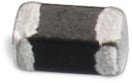 | SPECWE-CBF SMT-Ferrit, –, – | Verfügbarkeit – | Status Aktivi| Produktion ist aktiv. Erwartete Lebenszeit: >10 Jahre. | ProduktserieWE-CBF SMT-Ferrit | – | – | – | – | – | – | – | – | – | – | – | – | – | – | – | – | – | – | Bauform0402 | Betriebstemperatur -55 °C up to +125 °C | – | – | – | – | Länge1 mm | Breite0.5 mm | Höhe0.5 mm | Pad Dimension0.25 mm | – | – | – | – | – | – | MontageartSMT | Nennstrom250 mA | – | – | Impedanz @ 100 MHz470 Ω | Maximale Impedanz1200 Ω | Maximale Impedanz300 MHz | Nennstrom 2620 mA | Gleichstromwiderstand0.45 Ω | TypHochgeschwindigkeit | –Verfügbarkeit prüfen | |||||||||||||||||||||||||||||||||||||||||||||||||||||||||||||||||||||||||||||||||||||||||||||||||||||||||||||||||||||||||||||||||||||||||||||||||||||||||||||||||||||||||||||||||||||||||||||||||||||||||||||||||||||||||||||||||||||||||||||||||||||||||||||||||||||||||||||||||||||||||||||||||||||||||||||||||||||||||||||||||||||||||||||||||||||||||||||||||||||||||||||||||||||||||||||||||||||||||||||||||||||||||||||||||||||||||||||||||||||||||||||||||||||||||||||||||||||||||||||||||||||||||||||||||||||||||||||||||||||||||||||||||||||||||||||||||||||||||||||||||||||||||||||||||||||||||||||||||||||||||||||||||||||||||||||||||||||||||||||||||||||||||||||||||||||||||||||||||||||||||||||||||||||||||||||||||||||||||||||||||||||||||||||||||||||||||||||||||||||||||||||||||||||||||||||||||||||||||||||||||||||||||||||||||||||||||||||||||||||||||||||||||||||||||||||||||||||||||||||||||||||||||||||||||||||||||||||||||||||||||||||||||||||||||||||||||||||
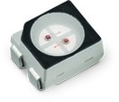 | SPECWL-SBTW SMT Bi-color TOP LED Waterclear, –, Rot & Hellgrün | Simulation– | Verfügbarkeit – | Downloads7 Dateien | Status Aktivi| Produktion ist aktiv. Erwartete Lebenszeit: >10 Jahre. | ProduktserieWL-SBTW SMT Bi-color TOP LED Waterclear | – | Emittierte FarbeRot & Hellgrün | – | Spitzen-Wellenlänge (Rot) [typ.]630 nm | Spitzen-Wellenlänge (Hellgrün) [typ.]572 nm | dominante Wellenlänge (Rot) [typ.]625 nm | dominante Wellenlänge (Bright Green) [typ.]570 nm | – | Lichtstärke (Rot) [typ.]250 mcd | Lichtstärke (Bright Green) [typ.]60 mcd | – | Durchlassspannung (Rot) [typ.]2 V | Durchlassspannung (Hellgrün) [typ.]2 V | ChiptechnologieAlInGaP | Abstrahlwinkel Phi 0° [typ.]120 ° | – | – | – | Bauform3528 | Betriebstemperatur -40 °C up to +85 °C | – | – | – | – | Länge3.5 mm | Breite2.8 mm | Höhe1.9 mm | – | VerpackungTape and Reel | – | – | – | – | – | MontageartSMT | – | – | – | – | – | – | – | – | – | –Verfügbarkeit prüfen | |||||||||||||||||||||||||||||||||||||||||||||||||||||||||||||||||||||||||||||||||||||||||||||||||||||||||||||||||||||||||||||||||||||||||||||||||||||||||||||||||||||||||||||||||||||||||||||||||||||||||||||||||||||||||||||||||||||||||||||||||||||||||||||||||||||||||||||||||||||||||||||||||||||||||||||||||||||||||||||||||||||||||||||||||||||||||||||||||||||||||||||||||||||||||||||||||||||||||||||||||||||||||||||||||||||||||||||||||||||||||||||||||||||||||||||||||||||||||||||||||||||||||||||||||||||||||||||||||||||||||||||||||||||||||||||||||||||||||||||||||||||||||||||||||||||||||||||||||||||||||||||||||||||||||||||||||||||||||||||||||||||||||||||||||||||||||||||||||||||||||||||||||||||||||||||||||||||||||||||||||||||||||||||||||||||||||||||||||||||||||||||||||||||||||||||||||||||||||||||||||||||||||||||||||||||||||||||||||||||||||||||||||||||||||||||||||||||||||||||||||||||||||||||||||||||||||||||||||||||||||||||||||||||||||||||||||||
SPECWCAP-CSGP MLCCs 16 V(DC), –, – | Verfügbarkeit – | Status Aktivi| Produktion ist aktiv. Erwartete Lebenszeit: >10 Jahre. | ProduktserieWCAP-CSGP MLCCs 16 V(DC) | – | – | – | – | – | – | – | – | – | – | – | – | – | – | – | Kapazität10 pF | Kapazität±5% | Nennspannung16 V (DC) | Bauform0402 | Betriebstemperatur -55 °C up to +125 °C | Güte600 | – | Isolationswiderstand10 GΩ | KeramiktypNP0 Klasse I | Länge1 mm | Breite0.5 mm | Höhe0.5 mm | Pad Dimension0.25 mm | Verpackung7" Tape & Reel | – | – | – | – | – | – | – | – | – | – | – | – | – | – | – | –Verfügbarkeit prüfen | ||||||||||||||||||||||||||||||||||||||||||||||||||||||||||||||||||||||||||||||||||||||||||||||||||||||||||||||||||||||||||||||||||||||||||||||||||||||||||||||||||||||||||||||||||||||||||||||||||||||||||||||||||||||||||||||||||||||||||||||||||||||||||||||||||||||||||||||||||||||||||||||||||||||||||||||||||||||||||||||||||||||||||||||||||||||||||||||||||||||||||||||||||||||||||||||||||||||||||||||||||||||||||||||||||||||||||||||||||||||||||||||||||||||||||||||||||||||||||||||||||||||||||||||||||||||||||||||||||||||||||||||||||||||||||||||||||||||||||||||||||||||||||||||||||||||||||||||||||||||||||||||||||||||||||||||||||||||||||||||||||||||||||||||||||||||||||||||||||||||||||||||||||||||||||||||||||||||||||||||||||||||||||||||||||||||||||||||||||||||||||||||||||||||||||||||||||||||||||||||||||||||||||||||||||||||||||||||||||||||||||||||||||||||||||||||||||||||||||||||||||||||||||||||||||||||||||||||||||||||||||||||||||||||||||||||||||||||
SPECWCAP-CSGP MLCCs 16 V(DC), –, – | Verfügbarkeit – | Status Aktivi| Produktion ist aktiv. Erwartete Lebenszeit: >10 Jahre. | ProduktserieWCAP-CSGP MLCCs 16 V(DC) | – | – | – | – | – | – | – | – | – | – | – | – | – | – | – | Kapazität10 pF | Kapazität±5% | Nennspannung16 V (DC) | Bauform0603 | Betriebstemperatur -55 °C up to +125 °C | Güte600 | – | Isolationswiderstand10 GΩ | KeramiktypNP0 Klasse I | Länge1.6 mm | Breite0.8 mm | Höhe0.8 mm | Pad Dimension0.4 mm | Verpackung7" Tape & Reel | – | – | – | – | – | – | – | – | – | – | – | – | – | – | – | –Verfügbarkeit prüfen | ||||||||||||||||||||||||||||||||||||||||||||||||||||||||||||||||||||||||||||||||||||||||||||||||||||||||||||||||||||||||||||||||||||||||||||||||||||||||||||||||||||||||||||||||||||||||||||||||||||||||||||||||||||||||||||||||||||||||||||||||||||||||||||||||||||||||||||||||||||||||||||||||||||||||||||||||||||||||||||||||||||||||||||||||||||||||||||||||||||||||||||||||||||||||||||||||||||||||||||||||||||||||||||||||||||||||||||||||||||||||||||||||||||||||||||||||||||||||||||||||||||||||||||||||||||||||||||||||||||||||||||||||||||||||||||||||||||||||||||||||||||||||||||||||||||||||||||||||||||||||||||||||||||||||||||||||||||||||||||||||||||||||||||||||||||||||||||||||||||||||||||||||||||||||||||||||||||||||||||||||||||||||||||||||||||||||||||||||||||||||||||||||||||||||||||||||||||||||||||||||||||||||||||||||||||||||||||||||||||||||||||||||||||||||||||||||||||||||||||||||||||||||||||||||||||||||||||||||||||||||||||||||||||||||||||||||||||||
SPECWCAP-CSGP MLCCs 50 V(DC), –, – | Verfügbarkeit – | Status Aktivi| Produktion ist aktiv. Erwartete Lebenszeit: >10 Jahre. | ProduktserieWCAP-CSGP MLCCs 50 V(DC) | – | – | – | – | – | – | – | – | – | – | – | – | – | – | – | Kapazität15 pF | Kapazität±5% | Nennspannung50 V (DC) | Bauform0603 | Betriebstemperatur -55 °C up to +125 °C | Güte700 | – | Isolationswiderstand10 GΩ | KeramiktypNP0 Klasse I | Länge1.6 mm | Breite0.8 mm | Höhe0.8 mm | Pad Dimension0.4 mm | Verpackung7" Tape & Reel | – | – | – | – | – | – | – | – | – | – | – | – | – | – | – | –Verfügbarkeit prüfen | ||||||||||||||||||||||||||||||||||||||||||||||||||||||||||||||||||||||||||||||||||||||||||||||||||||||||||||||||||||||||||||||||||||||||||||||||||||||||||||||||||||||||||||||||||||||||||||||||||||||||||||||||||||||||||||||||||||||||||||||||||||||||||||||||||||||||||||||||||||||||||||||||||||||||||||||||||||||||||||||||||||||||||||||||||||||||||||||||||||||||||||||||||||||||||||||||||||||||||||||||||||||||||||||||||||||||||||||||||||||||||||||||||||||||||||||||||||||||||||||||||||||||||||||||||||||||||||||||||||||||||||||||||||||||||||||||||||||||||||||||||||||||||||||||||||||||||||||||||||||||||||||||||||||||||||||||||||||||||||||||||||||||||||||||||||||||||||||||||||||||||||||||||||||||||||||||||||||||||||||||||||||||||||||||||||||||||||||||||||||||||||||||||||||||||||||||||||||||||||||||||||||||||||||||||||||||||||||||||||||||||||||||||||||||||||||||||||||||||||||||||||||||||||||||||||||||||||||||||||||||||||||||||||||||||||||||||||||
SPECWCAP-CSGP MLCCs 25 V(DC), –, – | Verfügbarkeit – | Status Aktivi| Produktion ist aktiv. Erwartete Lebenszeit: >10 Jahre. | ProduktserieWCAP-CSGP MLCCs 25 V(DC) | – | – | – | – | – | – | – | – | – | – | – | – | – | – | – | Kapazität470 nF | Kapazität±10% | Nennspannung25 V (DC) | Bauform0603 | Betriebstemperatur -55 °C up to +125 °C | – | Verlustfaktor10 % | Isolationswiderstand1.1 GΩ | KeramiktypX7R Klasse II | Länge1.6 mm | Breite0.8 mm | Höhe0.8 mm | Pad Dimension0.4 mm | Verpackung7" Tape & Reel | – | – | – | – | – | – | – | – | – | – | – | – | – | – | – | –Verfügbarkeit prüfen | ||||||||||||||||||||||||||||||||||||||||||||||||||||||||||||||||||||||||||||||||||||||||||||||||||||||||||||||||||||||||||||||||||||||||||||||||||||||||||||||||||||||||||||||||||||||||||||||||||||||||||||||||||||||||||||||||||||||||||||||||||||||||||||||||||||||||||||||||||||||||||||||||||||||||||||||||||||||||||||||||||||||||||||||||||||||||||||||||||||||||||||||||||||||||||||||||||||||||||||||||||||||||||||||||||||||||||||||||||||||||||||||||||||||||||||||||||||||||||||||||||||||||||||||||||||||||||||||||||||||||||||||||||||||||||||||||||||||||||||||||||||||||||||||||||||||||||||||||||||||||||||||||||||||||||||||||||||||||||||||||||||||||||||||||||||||||||||||||||||||||||||||||||||||||||||||||||||||||||||||||||||||||||||||||||||||||||||||||||||||||||||||||||||||||||||||||||||||||||||||||||||||||||||||||||||||||||||||||||||||||||||||||||||||||||||||||||||||||||||||||||||||||||||||||||||||||||||||||||||||||||||||||||||||||||||||||||||||
SPECWCAP-CSGP MLCCs 25 V(DC), –, – | Verfügbarkeit – | Status Aktivi| Produktion ist aktiv. Erwartete Lebenszeit: >10 Jahre. | ProduktserieWCAP-CSGP MLCCs 25 V(DC) | – | – | – | – | – | – | – | – | – | – | – | – | – | – | – | Kapazität1 µF | Kapazität±10% | Nennspannung25 V (DC) | Bauform0603 | Betriebstemperatur -55 °C up to +125 °C | – | Verlustfaktor10 % | Isolationswiderstand0.5 GΩ | KeramiktypX7R Klasse II | Länge1.6 mm | Breite0.8 mm | Höhe0.8 mm | Pad Dimension0.4 mm | Verpackung7" Tape & Reel | – | – | – | – | – | – | – | – | – | – | – | – | – | – | – | –Verfügbarkeit prüfen | ||||||||||||||||||||||||||||||||||||||||||||||||||||||||||||||||||||||||||||||||||||||||||||||||||||||||||||||||||||||||||||||||||||||||||||||||||||||||||||||||||||||||||||||||||||||||||||||||||||||||||||||||||||||||||||||||||||||||||||||||||||||||||||||||||||||||||||||||||||||||||||||||||||||||||||||||||||||||||||||||||||||||||||||||||||||||||||||||||||||||||||||||||||||||||||||||||||||||||||||||||||||||||||||||||||||||||||||||||||||||||||||||||||||||||||||||||||||||||||||||||||||||||||||||||||||||||||||||||||||||||||||||||||||||||||||||||||||||||||||||||||||||||||||||||||||||||||||||||||||||||||||||||||||||||||||||||||||||||||||||||||||||||||||||||||||||||||||||||||||||||||||||||||||||||||||||||||||||||||||||||||||||||||||||||||||||||||||||||||||||||||||||||||||||||||||||||||||||||||||||||||||||||||||||||||||||||||||||||||||||||||||||||||||||||||||||||||||||||||||||||||||||||||||||||||||||||||||||||||||||||||||||||||||||||||||||||||||
SPECWCAP-CSGP MLCCs 50 V(DC), –, – | Verfügbarkeit – | Status Aktivi| Produktion ist aktiv. Erwartete Lebenszeit: >10 Jahre. | ProduktserieWCAP-CSGP MLCCs 50 V(DC) | – | – | – | – | – | – | – | – | – | – | – | – | – | – | – | Kapazität100 nF | Kapazität±10% | Nennspannung50 V (DC) | Bauform0603 | Betriebstemperatur -55 °C up to +125 °C | – | Verlustfaktor3 % | Isolationswiderstand5 GΩ | KeramiktypX7R Klasse II | Länge1.6 mm | Breite0.8 mm | Höhe0.8 mm | Pad Dimension0.4 mm | Verpackung7" Tape & Reel | – | – | – | – | – | – | – | – | – | – | – | – | – | – | – | –Verfügbarkeit prüfen | ||||||||||||||||||||||||||||||||||||||||||||||||||||||||||||||||||||||||||||||||||||||||||||||||||||||||||||||||||||||||||||||||||||||||||||||||||||||||||||||||||||||||||||||||||||||||||||||||||||||||||||||||||||||||||||||||||||||||||||||||||||||||||||||||||||||||||||||||||||||||||||||||||||||||||||||||||||||||||||||||||||||||||||||||||||||||||||||||||||||||||||||||||||||||||||||||||||||||||||||||||||||||||||||||||||||||||||||||||||||||||||||||||||||||||||||||||||||||||||||||||||||||||||||||||||||||||||||||||||||||||||||||||||||||||||||||||||||||||||||||||||||||||||||||||||||||||||||||||||||||||||||||||||||||||||||||||||||||||||||||||||||||||||||||||||||||||||||||||||||||||||||||||||||||||||||||||||||||||||||||||||||||||||||||||||||||||||||||||||||||||||||||||||||||||||||||||||||||||||||||||||||||||||||||||||||||||||||||||||||||||||||||||||||||||||||||||||||||||||||||||||||||||||||||||||||||||||||||||||||||||||||||||||||||||||||||||||||
SPECWCAP-CSGP MLCCs 16 V(DC), –, – | Verfügbarkeit – | Status Aktivi| Produktion ist aktiv. Erwartete Lebenszeit: >10 Jahre. | ProduktserieWCAP-CSGP MLCCs 16 V(DC) | – | – | – | – | – | – | – | – | – | – | – | – | – | – | – | Kapazität10 µF | Kapazität±20% | Nennspannung16 V (DC) | Bauform0805 | Betriebstemperatur -55 °C up to +85 °C | – | Verlustfaktor10 % | Isolationswiderstand0.01 GΩ | KeramiktypX5R Klasse II | Länge2 mm | Breite1.25 mm | Höhe1.25 mm | Pad Dimension0.5 mm | Verpackung7" Tape & Reel | – | – | – | – | – | – | – | – | – | – | – | – | – | – | – | –Verfügbarkeit prüfen | ||||||||||||||||||||||||||||||||||||||||||||||||||||||||||||||||||||||||||||||||||||||||||||||||||||||||||||||||||||||||||||||||||||||||||||||||||||||||||||||||||||||||||||||||||||||||||||||||||||||||||||||||||||||||||||||||||||||||||||||||||||||||||||||||||||||||||||||||||||||||||||||||||||||||||||||||||||||||||||||||||||||||||||||||||||||||||||||||||||||||||||||||||||||||||||||||||||||||||||||||||||||||||||||||||||||||||||||||||||||||||||||||||||||||||||||||||||||||||||||||||||||||||||||||||||||||||||||||||||||||||||||||||||||||||||||||||||||||||||||||||||||||||||||||||||||||||||||||||||||||||||||||||||||||||||||||||||||||||||||||||||||||||||||||||||||||||||||||||||||||||||||||||||||||||||||||||||||||||||||||||||||||||||||||||||||||||||||||||||||||||||||||||||||||||||||||||||||||||||||||||||||||||||||||||||||||||||||||||||||||||||||||||||||||||||||||||||||||||||||||||||||||||||||||||||||||||||||||||||||||||||||||||||||||||||||||||||||
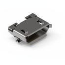 | SPECWR-USB Mini/Micro Connectors, –, – | Simulation– | Verfügbarkeit – | Status Aktivi| Produktion ist aktiv. Erwartete Lebenszeit: >10 Jahre. | ProduktserieWR-USB Mini/Micro Connectors | – | – | – | – | – | – | – | – | – | – | – | – | – | – | – | – | – | – | – | Betriebstemperatur -40 °C up to +105 °C | – | – | Isolationswiderstand1000 MΩ | – | – | – | – | – | VerpackungTape and Reel | AnwendungMicro USB 2.0 | Interface typType B | AusführungMit Pads & Pegs | GenderBuchse | Pins5 | MontageartSMT | Nennstrom1000 mA | Arbeitsspannung30 V (AC) | FarbeSchwarz | – | – | – | – | – | TypHorizontal | –Verfügbarkeit prüfen | ||||||||||||||||||||||||||||||||||||||||||||||||||||||||||||||||||||||||||||||||||||||||||||||||||||||||||||||||||||||||||||||||||||||||||||||||||||||||||||||||||||||||||||||||||||||||||||||||||||||||||||||||||||||||||||||||||||||||||||||||||||||||||||||||||||||||||||||||||||||||||||||||||||||||||||||||||||||||||||||||||||||||||||||||||||||||||||||||||||||||||||||||||||||||||||||||||||||||||||||||||||||||||||||||||||||||||||||||||||||||||||||||||||||||||||||||||||||||||||||||||||||||||||||||||||||||||||||||||||||||||||||||||||||||||||||||||||||||||||||||||||||||||||||||||||||||||||||||||||||||||||||||||||||||||||||||||||||||||||||||||||||||||||||||||||||||||||||||||||||||||||||||||||||||||||||||||||||||||||||||||||||||||||||||||||||||||||||||||||||||||||||||||||||||||||||||||||||||||||||||||||||||||||||||||||||||||||||||||||||||||||||||||||||||||||||||||||||||||||||||||||||||||||||||||||||||||||||||||||||||||||||||||||||||||||||||||||
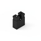 | SPECWR-PHD Kurzschlussbrücken, –, – | Simulation– | Verfügbarkeit – | Status Aktivi| Produktion ist aktiv. Erwartete Lebenszeit: >10 Jahre. | ProduktserieWR-PHD Kurzschlussbrücken | – | – | – | – | – | – | – | – | – | – | – | – | – | – | – | – | – | – | – | Betriebstemperatur -40 °C up to +125 °C | – | – | Isolationswiderstand1000 MΩ | – | Länge2.44 mm | – | – | – | VerpackungBeutel | – | – | – | GenderJumper | Pins1 | – | Nennstrom3000 mA | Arbeitsspannung250 V (AC) | FarbeSchwarz | – | – | – | – | – | – | –Verfügbarkeit prüfen | ||||||||||||||||||||||||||||||||||||||||||||||||||||||||||||||||||||||||||||||||||||||||||||||||||||||||||||||||||||||||||||||||||||||||||||||||||||||||||||||||||||||||||||||||||||||||||||||||||||||||||||||||||||||||||||||||||||||||||||||||||||||||||||||||||||||||||||||||||||||||||||||||||||||||||||||||||||||||||||||||||||||||||||||||||||||||||||||||||||||||||||||||||||||||||||||||||||||||||||||||||||||||||||||||||||||||||||||||||||||||||||||||||||||||||||||||||||||||||||||||||||||||||||||||||||||||||||||||||||||||||||||||||||||||||||||||||||||||||||||||||||||||||||||||||||||||||||||||||||||||||||||||||||||||||||||||||||||||||||||||||||||||||||||||||||||||||||||||||||||||||||||||||||||||||||||||||||||||||||||||||||||||||||||||||||||||||||||||||||||||||||||||||||||||||||||||||||||||||||||||||||||||||||||||||||||||||||||||||||||||||||||||||||||||||||||||||||||||||||||||||||||||||||||||||||||||||||||||||||||||||||||||||||||||||||||||||||
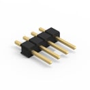 | SPECWR-PHD Stiftleisten - Einreihig, –, – | Simulation– | Verfügbarkeit – | Status Aktivi| Produktion ist aktiv. Erwartete Lebenszeit: >10 Jahre. | ProduktserieWR-PHD Stiftleisten - Einreihig | – | – | – | – | – | – | – | – | – | – | – | – | – | – | – | – | – | – | – | Betriebstemperatur -40 °C up to +105 °C | – | – | Isolationswiderstand1000 MΩ | – | Länge10.16 mm | – | – | – | VerpackungBeutel | – | – | – | GenderStiftleiste | Pins4 | MontageartTHT | Nennstrom3000 mA | Arbeitsspannung250 V (AC) | – | – | – | – | – | – | TypGerade | –Verfügbarkeit prüfen | ||||||||||||||||||||||||||||||||||||||||||||||||||||||||||||||||||||||||||||||||||||||||||||||||||||||||||||||||||||||||||||||||||||||||||||||||||||||||||||||||||||||||||||||||||||||||||||||||||||||||||||||||||||||||||||||||||||||||||||||||||||||||||||||||||||||||||||||||||||||||||||||||||||||||||||||||||||||||||||||||||||||||||||||||||||||||||||||||||||||||||||||||||||||||||||||||||||||||||||||||||||||||||||||||||||||||||||||||||||||||||||||||||||||||||||||||||||||||||||||||||||||||||||||||||||||||||||||||||||||||||||||||||||||||||||||||||||||||||||||||||||||||||||||||||||||||||||||||||||||||||||||||||||||||||||||||||||||||||||||||||||||||||||||||||||||||||||||||||||||||||||||||||||||||||||||||||||||||||||||||||||||||||||||||||||||||||||||||||||||||||||||||||||||||||||||||||||||||||||||||||||||||||||||||||||||||||||||||||||||||||||||||||||||||||||||||||||||||||||||||||||||||||||||||||||||||||||||||||||||||||||||||||||||||||||||||||||
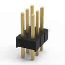 | SPECWR-PHD Stiftleisten - Zweireihig, –, – | Simulation– | Verfügbarkeit – | Status Aktivi| Produktion ist aktiv. Erwartete Lebenszeit: >10 Jahre. | ProduktserieWR-PHD Stiftleisten - Zweireihig | – | – | – | – | – | – | – | – | – | – | – | – | – | – | – | – | – | – | – | Betriebstemperatur -40 °C up to +105 °C | – | – | Isolationswiderstand1000 MΩ | – | Länge7.62 mm | – | – | – | VerpackungBeutel | – | – | – | GenderStiftleiste | Pins6 | MontageartTHT | Nennstrom3000 mA | Arbeitsspannung250 V (AC) | – | – | – | – | – | – | TypGerade | –Verfügbarkeit prüfen | ||||||||||||||||||||||||||||||||||||||||||||||||||||||||||||||||||||||||||||||||||||||||||||||||||||||||||||||||||||||||||||||||||||||||||||||||||||||||||||||||||||||||||||||||||||||||||||||||||||||||||||||||||||||||||||||||||||||||||||||||||||||||||||||||||||||||||||||||||||||||||||||||||||||||||||||||||||||||||||||||||||||||||||||||||||||||||||||||||||||||||||||||||||||||||||||||||||||||||||||||||||||||||||||||||||||||||||||||||||||||||||||||||||||||||||||||||||||||||||||||||||||||||||||||||||||||||||||||||||||||||||||||||||||||||||||||||||||||||||||||||||||||||||||||||||||||||||||||||||||||||||||||||||||||||||||||||||||||||||||||||||||||||||||||||||||||||||||||||||||||||||||||||||||||||||||||||||||||||||||||||||||||||||||||||||||||||||||||||||||||||||||||||||||||||||||||||||||||||||||||||||||||||||||||||||||||||||||||||||||||||||||||||||||||||||||||||||||||||||||||||||||||||||||||||||||||||||||||||||||||||||||||||||||||||||||||||||
| Erwartete Verfügbarkeit | Eingehender Bestand | Menge |
|---|---|---|
| Aktuelle Verfügbarkeit | – | – |