OverviewAll product unitsProduct unitPassive ComponentsProduct groupSignal & CommunicationsProduct familyRF Inductors

What is the Quality Factor Q?

The quality factor Q is an essential characteristic parameter and one of the first creterias that every RF engineer should take into account. The Q factor is given either as minimum or as typical value at a defined frequency point. In the case of Würth Elektronik, the Q factor is given as the minimum value in order to guarantee customers a reliable minimum level.

Basically, the Q factor is the ratio between the inductive reactance XL and the losses RS and is an indicator of how ideal an inductor is. For inductors with air or ceramic cores, the resistance RS is mainly due to the resistivity of the conductor in the inductor device. A higher Q factor means less losses in the component.

Self Resonant Frequency

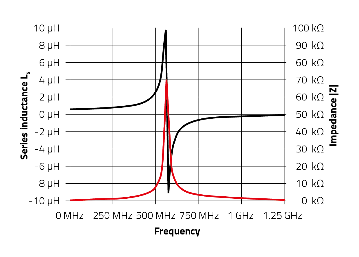
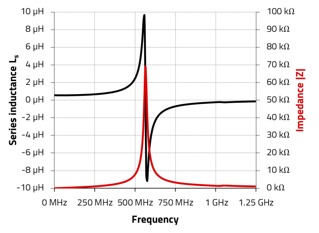
Because the winding structure of any coil of wire will exhibit some capacitance, the inductor will serve as a parallel resonant tank circuit with an associated self-resonance frequency (SRF). As with conventional inductors, SRF indicates up to which frequency the inductor behaves as an inductor.

Exactly at the SRF the inductor with its parasitic capacitance behaves as a resonance circuit with an almost infinite high impedance, only circuit losses limit the high value of the impedance. Beyond the SRF the “inductor” behaves like a capacitor

Increasing the inductance and/or the parasitic capacitance lowers the SRF, and vice versa. This is the reason why the higher the inductance value, the lower the SRF.

In case of choke applications in which inductors are used, the best signal blocking occurs shortly below the SRF, where the impedance is very high and thus the attenuation reaches its maximum. For filter or impedance-matching applications, it is more important to have constant inductance in the relevant frequency range, which means the SRF of the inductor should be well above the operating frequency of the circuit.

Rated Current in high frequency application

The rated current is specified as the maximum DC current (A or mA) that causes a defined temperature rise (i.e. ΔT = 40 K). The temperature rise plus the ambient temperature must not exceed the maximum operating temperature. For high current applications, please select the specific air core inductors: WE-KI HC, WE-ACHC and WE-CAIR.

RF inductors and Antenna Matching

How Antenna Matching works

With the help of the Smith chart, the complex antenna feed point impedance, consisting of resistive and reactive values, can be represented graphically. In a matched antenna, the impedance at the operating frequency is close to the middle of the Smith chart and therefore close to the impedance of 50 Ω. This can be achieved by using RF inductors and RF capacitors. A pi matching network is particularly useful for this purpose, since it can be used flexibly for antenna matching from almost any other impedance. In practice, antenna matching works through iterative steps.

In addition to the WE-MCA Antennas, we offer our customers a development-accompanying antenna service. We support from the antenna selection over the antenna placement up to the antenna matching.

Website: www.we-online.com/antenna-matching

E-Mail: antenna.matching@we-online.com

We are also offering an Antenna Matching Design Kit that contains all the components needed for your antenna matching. This Design Kit with order code 748001, contains chip antennas WE-MCA, multilayer ceramic inductors WE-MK size 0402, high frequency chip capacitors WCAP-CSRF in size 0402 and RF coaxial cables WR-CXARY working up to 18 GHz