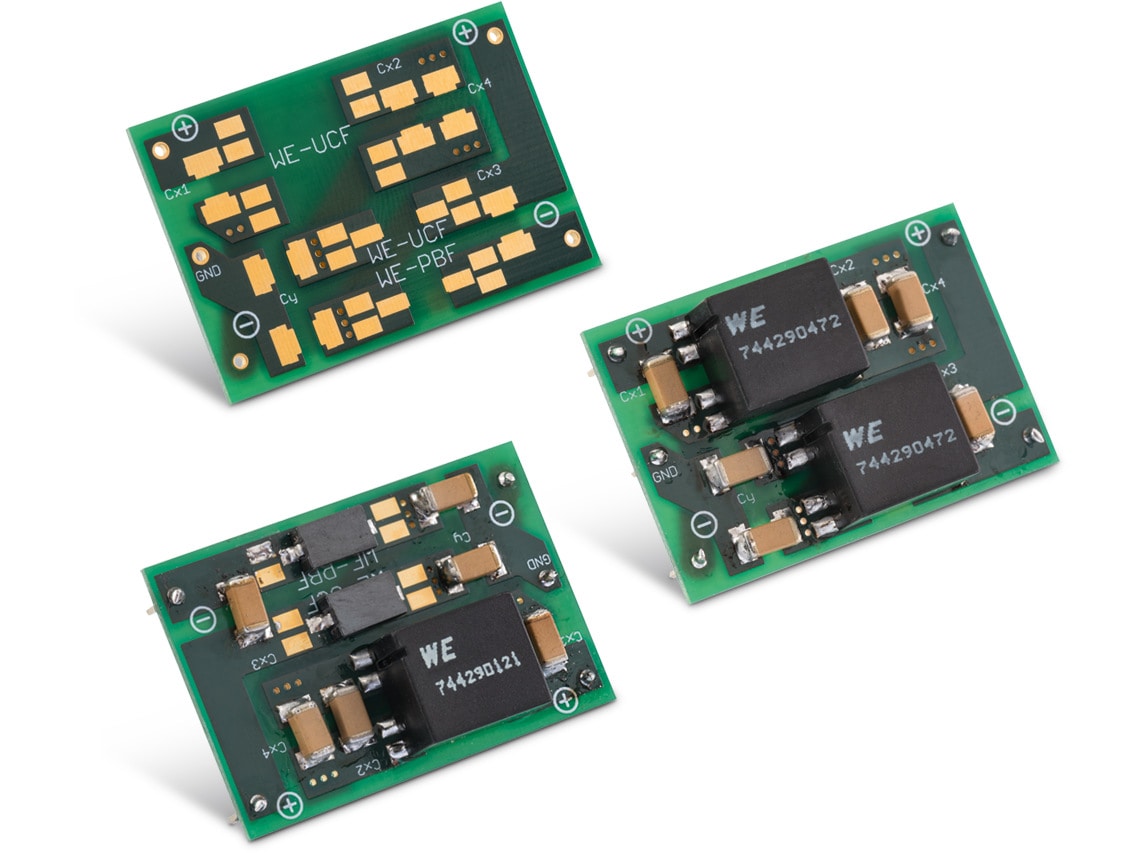
Evaluation Board DC 2stepCMC Filter
Order Code 7449983
Characteristics
- Printed circuit board for evaluation of different EMC-filters
- To evaluate and select different filter components for the best possible common and differential mode attenuation for your application
- Multi land pattern for ceramic SMT capacitors
- Variable use of differential chokes or a second CMC for higher differential or common mode suppression
- SMT (Surface Mount Technology) mounting
- Components are not included!
Applications
- DC applications up to 80 V
- Important information: This is an evaluation board. The board should not be installed in the final application.
Find filter solutions quickly and cost-effectively with the
Evaluation Board
Find filter solutions quickly and cost-effectively with the
Evaluation Board
This PCB offers a fast and cost-effective means of building up the filter design with various components. It allows for the examination of the filter circuit's performance in relation to the desired filtering effect, facilitating the seamless integration of the chosen filter circuit into the application. This can reduce development time and the associated costs.
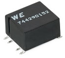
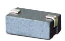
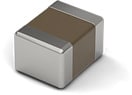
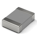
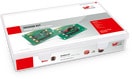
The evaluation board can be used as a supplement to the Design Your EMC-Filter Design Kit or independently with the components shown in the adjacent figure and below.

2-stage Pi filter for differential mode attenuation

Schematic with second Common Mode Choke
The X-Capacitors (CX1–CX4) and the Leakage Inductances (LLeak1 and LLeak2) of the Common Mode Chokes build a low-pass for high frequency differential mode interferences. While X-Capacitors divert high-frequency interference via N in the direction of the interference source, it is attenuated by the Common Mode Choke.

Schematic with two Differential Chokes
In this circuit the Common Mode Choke (CMC2) is replaced by two Differential Chokes (L1 and L2). Since the impedances that the Differential Chokes bring against the differential interference are higher than those of the Leakage Inductances of the Common Mode Choke, the differential mode attenuation with Differential Chokes is higher.
T-filter for common mode attenuation

Schematic with two Differential Chokes
In this circuit, the Common Mode Choke (CMC1), the Y-Capacitors (CY1, CY2) and the Differential Chokes (L1, L2) built a low-pass filter. While Y-Capacitors divert high-frequency interference via ground, it is attenuated by the Common Mode Choke and the Differential Chokes. For pure common mode interference, this setup is not the best solution, since the Differential Chokes can affect the useful signal.

Schematic with second Common Mode Choke
If the two Differential Chokes (L1 and L2) are replaced by a Common Mode Choke (CMC2), better common mode rejection can be achieved without attenuating the useful signal.