IC-Hersteller (105)
- Alle Hersteller
 Analog Devices
 Infineon Technologies
 Microchip
 Onsemi
 Renesas
 ROHM
ROHM STMicroelectronics
 Texas Instruments
- 3peak incorporated (35)
- Ablic (23)
- Acco Semiconductor (1)
- Advanced Power (4)
- Allegro Microsystems (100)
- Alpha & Omega Semiconductor (37)
- AnalogySemi (3)
- AnDAPT Inc (204)
- Anpec (13)
- AXElite (2)
- Backward (6)
- Bright Power Semiconductor (1)
- Broadcom (46)
- Cambridge GaN Devices (18)
- Chipanalog Micro (10)
- Cologne Chips (1)
- Convenient Power (1)
- Dialog Semiconductor (12)
- Diodes Incorporated (257)
- Divimath (8)
- Elmos AG (1)
- EPC (146)
- e-Peas Semiconductors (1)
- Eta Solutions Co. Ltd. (9)
- GaN Systems (8)
- GaNPower (3)
- Giantec (1)
- Gstek Wuxi (1)
- Helix Semiconductor (7)
- IKON (1)
- Indie Semiconductor (8)
- Innovision Semiconductor Inc (2)
- Intel (68)
- Inventchip Technology (3)
- ISSI (51)
- JoulWatt (20)
- KDPOF (3)
- Kinetic Technology (8)
- Lattice semiconductor Corporation (38)
- Littelfuse (1)
- Lumissil Microsystems (8)
- M3 Technology (M3Tek) (7)
- Macnica (22)
- Marvell Semiconductor (1)
- MaxLinear (181)
- Menlo Micro (1)
- MikroE (25)
- MindCet (2)
- Monolithic Power Systems (982)
- Navitas Semiconductor Inc (6)
- NewEdge Technologies, Inc. (1)
- Nexperia (268)
- Nisshinbo Micro Device Inc. (10)
- Nordic Semiconductor (1)
- Novosense Micro (1)
- NXP (341)
- O2 Micro International Ltd (10)
- On Bright (7)
- Panasonic (2)
- PN Junction Semiconductor (2)
- Power Integrations (117)
- Powermat (1)
- Pulsiv (19)
- Qorvo (99)
- Realsil SuRealsil(tek) Microelectronics (1)
- Richtek (297)
- Sanken Electric Co., Ltd. (16)
- Sckipio (6)
- Semtech (86)
- SG-Micro (58)
- SiFive (2)
- Silanna Semiconductor (9)
- Silergy Corporation (34)
- Silicon Laboratory Inc. (108)
- Silicontent Technology (59)
- Silvertel (59)
- Skycore Semiconductors (1)
- Skyworks (33)
- Southchip (18)
- Summit Wireless (1)
- Tagore Tech (7)
- Taiwan Semiconductor (1)
- TDK Corporation (1)
- Tempo Semiconductor (1)
- Torex (37)
- Toshiba (27)
- Transphorm (21)
- TransSIP (2)
- Union (21)
- uPI Semiconductor (2)
- Valens Semiconductor (31)
- VisIC (1)
- Wise Integration (3)
- Wolfspeed (23)
- Xilinx (22)
- XL Semiconductor (3)
- XYSemi (62)
Details
| Topologie | Sonstige Topologie |
| IC-Revision | 1.0 |
Beschreibung
The X-NUCLEO-60K1A1 is a kit composed of two expansion boards, an X-NUCLEO-60L1A1 expansion board, and an X-NUCLEO-60R1A1 expansion board, working as a pair, which can be plugged onto most STM32 Nucleo board equipped with the Arduino R3 connectors. It provides a complete evaluation kit that allows you to learn, evaluate, and develop applications based on the ST60A3H1 transceiver, for contactless connectivity up to 480 Mbit/s.The ST60A3H1 is a full RF transceiver with a dual-linear-polarization integrated antenna, operating in half-duplex mode. It provides an optimized solution for a high-speed, low-power, short-range point to point 60 GHz RF link.The X-NUCLEO-60L1A1 expansion board, which hosts an ST60A3H1 configured as Local is the only board needing to be plugged onto an STM32 Nucleo development board (for example, NUCLEO-L476RG with ultralow power STM32 microcontroller). The other X-NUCLEO-60R1A1 expansion board, which hosts an ST60A3H1 configured as Remote is used in standalone. Any ST60A3H1 configuration is done from the X-NUCLEO-60L1A1 side.
Eigenschaften
60 GHz V-band contactless connectivity transceiver expansion board kit, based on the ST60A3H1 for STM32 Nucleo. The X-NUCLEO-60K1A1 kit is composed of two boards:X-NUCLEO-60L1A1 expansion board with an ST60A3H1 configured as LocalX-NUCLEO-60R1A1 expansion board with an ST60A3H1 configured as RemoteRange up to 3 cmeUSB2, UART, GPIO, or I²C RF tunnelingEmbedded eUSB2 repeaterBypassable USB2 hub on Remote ST60A3H1 sideCompatible with most STM32 Nucleo boardsEquipped with Arduino® UNO R3 connectorFree comprehensive development firmware library and examples for ST60A3H1, compatible with STM32CubeETSI certifiedRoHS, CE, and UKCA compliant
Typische Anwendungen
- Contactless connectivity up to 480 Mbit/s
Weiterführende Informationen
Artikeldaten
Artikel Nr. | Datenblatt | Simulation | Downloads | Status | Produktserie | C | Tol. C | VR(V (DC)) | Bauform | Betriebstemperatur | RISO | Keramiktyp | L(mm) | B(mm) | Fl(mm) | Verpackung | Q | DF(%) | Anwendung | Interface typ | Gender | Pins | Montageart | Leiterplattendicke(mm) | Arbeitsspannung(V (DC)) | Z @ 100 MHz(Ω) | Zmax(Ω) | Testbedingung Zmax | IR(mA) | Z @ 1 GHz(Ω) | H(mm) | Typ | MusterVerfügbarkeit & Muster | |||||||||||||||||||||||||||||||||||||||||||||||||||||||||||||||||||||||||||||||||||||||||||||||||||||||||||||||||||||||||||||||||||||||||||||||||||||||||||||||||||||||||||||||||||||||||||||||||||||||||||||||||||||||||||||||||||||||||||||||||||||||||||||||||||||||||||||||||||||||||||||||||||||||||||||||||||||||||||||||||||||||||||||||||||||||||||||||||||||||||||||||||||||||||||||||||||||||||||||||||||||||||||||||||||||||||||||||||||||||||||||||||||||||||||||||||||||||||||||||||||||||||||||||||||||||||||||||||||||||||||||||||||||||||||||||||||||||||||||||||||||||||||||||||||||||||||||||||||||||||||||||||||||||||||||||||||||||||||||||||||||||||||||||||||||||||||||||||||||||||||||||||||||||||||||||||||||||||||||||||||||||||||||||||||||||||||||||||||||||||||||||||||||||||||||||||||||||||||||||||||||||||||||||||||||||||||||||||||||||||||||||||||||||||||||||||||||||||||||||||||||||||||||||||||||||||||||||||||||||||||||||||||||||||||||||||||||||||||||||||||||
|---|---|---|---|---|---|---|---|---|---|---|---|---|---|---|---|---|---|---|---|---|---|---|---|---|---|---|---|---|---|---|---|---|---|---|---|---|---|---|---|---|---|---|---|---|---|---|---|---|---|---|---|---|---|---|---|---|---|---|---|---|---|---|---|---|---|---|---|---|---|---|---|---|---|---|---|---|---|---|---|---|---|---|---|---|---|---|---|---|---|---|---|---|---|---|---|---|---|---|---|---|---|---|---|---|---|---|---|---|---|---|---|---|---|---|---|---|---|---|---|---|---|---|---|---|---|---|---|---|---|---|---|---|---|---|---|---|---|---|---|---|---|---|---|---|---|---|---|---|---|---|---|---|---|---|---|---|---|---|---|---|---|---|---|---|---|---|---|---|---|---|---|---|---|---|---|---|---|---|---|---|---|---|---|---|---|---|---|---|---|---|---|---|---|---|---|---|---|---|---|---|---|---|---|---|---|---|---|---|---|---|---|---|---|---|---|---|---|---|---|---|---|---|---|---|---|---|---|---|---|---|---|---|---|---|---|---|---|---|---|---|---|---|---|---|---|---|---|---|---|---|---|---|---|---|---|---|---|---|---|---|---|---|---|---|---|---|---|---|---|---|---|---|---|---|---|---|---|---|---|---|---|---|---|---|---|---|---|---|---|---|---|---|---|---|---|---|---|---|---|---|---|---|---|---|---|---|---|---|---|---|---|---|---|---|---|---|---|---|---|---|---|---|---|---|---|---|---|---|---|---|---|---|---|---|---|---|---|---|---|---|---|---|---|---|---|---|---|---|---|---|---|---|---|---|---|---|---|---|---|---|---|---|---|---|---|---|---|---|---|---|---|---|---|---|---|---|---|---|---|---|---|---|---|---|---|---|---|---|---|---|---|---|---|---|---|---|---|---|---|---|---|---|---|---|---|---|---|---|---|---|---|---|---|---|---|---|---|---|---|---|---|---|---|---|---|---|---|---|---|---|---|---|---|---|---|---|---|---|---|---|---|---|---|---|---|---|---|---|---|---|---|---|---|---|---|---|---|---|---|---|---|---|---|---|---|---|---|---|---|---|---|---|---|---|---|---|---|---|---|---|---|---|---|---|---|---|---|---|---|---|---|---|---|---|---|---|---|---|---|---|---|---|---|---|---|---|---|---|---|---|---|---|---|---|---|---|---|---|---|---|---|---|---|---|---|---|---|---|---|---|---|---|---|---|---|---|---|---|---|---|---|---|---|---|---|---|---|---|---|---|---|---|---|---|---|---|---|---|---|---|---|---|---|---|---|---|---|---|---|---|---|---|---|---|---|---|---|---|---|---|---|---|---|---|---|---|---|---|---|---|---|---|---|---|---|---|---|---|---|---|---|---|---|---|---|---|---|---|---|---|---|---|---|---|---|---|---|---|---|---|---|---|---|---|---|---|---|---|---|---|---|---|---|---|---|---|---|---|---|---|---|---|---|---|---|---|---|---|---|---|---|---|---|---|---|---|---|---|---|---|---|---|---|---|---|---|---|---|---|---|---|---|---|---|---|---|---|---|---|---|---|---|---|---|---|---|---|---|---|---|---|---|---|---|---|---|---|---|---|---|---|---|---|---|---|---|---|---|---|---|---|---|---|---|---|---|---|---|---|---|---|---|---|---|---|---|---|---|---|---|---|---|---|---|---|---|---|---|---|---|---|---|---|---|---|---|---|---|---|---|---|---|---|---|---|---|---|---|---|---|---|---|---|---|---|---|---|---|---|---|---|---|---|---|---|---|---|---|---|---|---|---|---|---|---|---|---|---|---|---|---|---|---|---|---|---|---|---|---|---|---|---|---|---|---|---|---|---|---|---|---|---|---|---|---|---|---|---|---|---|---|---|---|---|---|---|---|---|---|---|---|---|---|---|---|---|---|---|---|---|---|---|---|---|---|---|---|---|---|---|---|---|---|---|---|---|---|---|---|---|---|---|---|---|---|---|---|---|---|---|---|---|---|---|---|---|---|---|---|---|---|---|---|---|---|---|---|---|---|---|---|---|---|---|---|---|---|---|---|---|---|---|---|---|---|---|---|---|---|---|---|---|---|---|---|---|---|---|---|---|---|---|---|---|---|---|---|---|---|---|---|---|---|---|---|---|---|---|---|---|---|---|---|---|---|---|---|---|---|---|---|---|---|---|---|---|---|---|---|---|---|---|---|---|---|---|---|---|---|---|---|---|---|---|---|---|---|---|---|---|---|---|---|---|---|---|---|---|---|---|---|---|---|---|---|---|---|---|
| Jetzt einloggen, um Verfügbarkeiten zu sehen und Verfügbarkeitsprognosen anzufragen. LOGIN | ||||||||||||||||||||||||||||||||||||||||||||||||||||||||||||||||||||||||||||||||||||||||||||||||||||||||||||||||||||||||||||||||||||||||||||||||||||||||||||||||||||||||||||||||||||||||||||||||||||||||||||||||||||||||||||||||||||||||||||||||||||||||||||||||||||||||||||||||||||||||||||||||||||||||||||||||||||||||||||||||||||||||||||||||||||||||||||||||||||||||||||||||||||||||||||||||||||||||||||||||||||||||||||||||||||||||||||||||||||||||||||||||||||||||||||||||||||||||||||||||||||||||||||||||||||||||||||||||||||||||||||||||||||||||||||||||||||||||||||||||||||||||||||||||||||||||||||||||||||||||||||||||||||||||||||||||||||||||||||||||||||||||||||||||||||||||||||||||||||||||||||||||||||||||||||||||||||||||||||||||||||||||||||||||||||||||||||||||||||||||||||||||||||||||||||||||||||||||||||||||||||||||||||||||||||||||||||||||||||||||||||||||||||||||||||||||||||||||||||||||||||||||||||||||||||||||||||||||||||||||||||||||||||||||||||||||||||||||||||||||||||||||||||||||||||||||||||||||||||||
SPECWCAP-CSRF High Frequency, 6.8 pF, ±0.1pF | Verfügbarkeit – | Status Aktivi| Produktion ist aktiv. Erwartete Lebenszeit: >10 Jahre. | ProduktserieWCAP-CSRF High Frequency | Kapazität6.8 pF | Kapazität±0.1pF | Nennspannung50 V (DC) | Bauform0402 | Betriebstemperatur -55 °C up to +125 °C | Isolationswiderstand10 GΩ | KeramiktypNP0 Klasse I | Länge1 mm | Breite0.5 mm | Pad Dimension0.25 mm | Verpackung7" Tape & Reel | Güte536 | – | – | – | – | – | – | – | – | – | – | – | – | – | Höhe0.5 mm | – | –Verfügbarkeit prüfen | |||||||||||||||||||||||||||||||||||||||||||||||||||||||||||||||||||||||||||||||||||||||||||||||||||||||||||||||||||||||||||||||||||||||||||||||||||||||||||||||||||||||||||||||||||||||||||||||||||||||||||||||||||||||||||||||||||||||||||||||||||||||||||||||||||||||||||||||||||||||||||||||||||||||||||||||||||||||||||||||||||||||||||||||||||||||||||||||||||||||||||||||||||||||||||||||||||||||||||||||||||||||||||||||||||||||||||||||||||||||||||||||||||||||||||||||||||||||||||||||||||||||||||||||||||||||||||||||||||||||||||||||||||||||||||||||||||||||||||||||||||||||||||||||||||||||||||||||||||||||||||||||||||||||||||||||||||||||||||||||||||||||||||||||||||||||||||||||||||||||||||||||||||||||||||||||||||||||||||||||||||||||||||||||||||||||||||||||||||||||||||||||||||||||||||||||||||||||||||||||||||||||||||||||||||||||||||||||||||||||||||||||||||||||||||||||||||||||||||||||||||||||||||||||||||||||||||||||||||||||||||||||||||||||||||||||||||||||||||||||||||||||
SPECWCAP-CSGP MLCCs 50 V(DC), 100 pF, ±5% | Verfügbarkeit – | Status Aktivi| Produktion ist aktiv. Erwartete Lebenszeit: >10 Jahre. | ProduktserieWCAP-CSGP MLCCs 50 V(DC) | Kapazität100 pF | Kapazität±5% | Nennspannung50 V (DC) | Bauform0402 | Betriebstemperatur -55 °C up to +125 °C | Isolationswiderstand10 GΩ | KeramiktypNP0 Klasse I | Länge1 mm | Breite0.5 mm | Pad Dimension0.25 mm | Verpackung7" Tape & Reel | Güte1000 | – | – | – | – | – | – | – | – | – | – | – | – | – | Höhe0.5 mm | – | –Verfügbarkeit prüfen | |||||||||||||||||||||||||||||||||||||||||||||||||||||||||||||||||||||||||||||||||||||||||||||||||||||||||||||||||||||||||||||||||||||||||||||||||||||||||||||||||||||||||||||||||||||||||||||||||||||||||||||||||||||||||||||||||||||||||||||||||||||||||||||||||||||||||||||||||||||||||||||||||||||||||||||||||||||||||||||||||||||||||||||||||||||||||||||||||||||||||||||||||||||||||||||||||||||||||||||||||||||||||||||||||||||||||||||||||||||||||||||||||||||||||||||||||||||||||||||||||||||||||||||||||||||||||||||||||||||||||||||||||||||||||||||||||||||||||||||||||||||||||||||||||||||||||||||||||||||||||||||||||||||||||||||||||||||||||||||||||||||||||||||||||||||||||||||||||||||||||||||||||||||||||||||||||||||||||||||||||||||||||||||||||||||||||||||||||||||||||||||||||||||||||||||||||||||||||||||||||||||||||||||||||||||||||||||||||||||||||||||||||||||||||||||||||||||||||||||||||||||||||||||||||||||||||||||||||||||||||||||||||||||||||||||||||||||||||||||||||||||||
SPECWCAP-CSGP MLCCs 50 V(DC), 10 nF, ±10% | Verfügbarkeit – | Status Aktivi| Produktion ist aktiv. Erwartete Lebenszeit: >10 Jahre. | ProduktserieWCAP-CSGP MLCCs 50 V(DC) | Kapazität10 nF | Kapazität±10% | Nennspannung50 V (DC) | Bauform0402 | Betriebstemperatur -55 °C up to +125 °C | Isolationswiderstand10 GΩ | KeramiktypX7R Klasse II | Länge1 mm | Breite0.5 mm | Pad Dimension0.25 mm | Verpackung7" Tape & Reel | – | Verlustfaktor2.5 % | – | – | – | – | – | – | – | – | – | – | – | – | Höhe0.5 mm | – | –Verfügbarkeit prüfen | |||||||||||||||||||||||||||||||||||||||||||||||||||||||||||||||||||||||||||||||||||||||||||||||||||||||||||||||||||||||||||||||||||||||||||||||||||||||||||||||||||||||||||||||||||||||||||||||||||||||||||||||||||||||||||||||||||||||||||||||||||||||||||||||||||||||||||||||||||||||||||||||||||||||||||||||||||||||||||||||||||||||||||||||||||||||||||||||||||||||||||||||||||||||||||||||||||||||||||||||||||||||||||||||||||||||||||||||||||||||||||||||||||||||||||||||||||||||||||||||||||||||||||||||||||||||||||||||||||||||||||||||||||||||||||||||||||||||||||||||||||||||||||||||||||||||||||||||||||||||||||||||||||||||||||||||||||||||||||||||||||||||||||||||||||||||||||||||||||||||||||||||||||||||||||||||||||||||||||||||||||||||||||||||||||||||||||||||||||||||||||||||||||||||||||||||||||||||||||||||||||||||||||||||||||||||||||||||||||||||||||||||||||||||||||||||||||||||||||||||||||||||||||||||||||||||||||||||||||||||||||||||||||||||||||||||||||||||||||||||||||||||
SPECWCAP-CSGP MLCCs 16 V(DC), 100 nF, ±10% | Verfügbarkeit – | Downloads7 Dateien | Status Aktivi| Produktion ist aktiv. Erwartete Lebenszeit: >10 Jahre. | ProduktserieWCAP-CSGP MLCCs 16 V(DC) | Kapazität100 nF | Kapazität±10% | Nennspannung16 V (DC) | Bauform0402 | Betriebstemperatur -55 °C up to +125 °C | Isolationswiderstand5 GΩ | KeramiktypX7R Klasse II | Länge1 mm | Breite0.5 mm | Pad Dimension0.25 mm | Verpackung7" Tape & Reel | – | Verlustfaktor5 % | – | – | – | – | – | – | – | – | – | – | – | – | Höhe0.5 mm | – | –Verfügbarkeit prüfen | ||||||||||||||||||||||||||||||||||||||||||||||||||||||||||||||||||||||||||||||||||||||||||||||||||||||||||||||||||||||||||||||||||||||||||||||||||||||||||||||||||||||||||||||||||||||||||||||||||||||||||||||||||||||||||||||||||||||||||||||||||||||||||||||||||||||||||||||||||||||||||||||||||||||||||||||||||||||||||||||||||||||||||||||||||||||||||||||||||||||||||||||||||||||||||||||||||||||||||||||||||||||||||||||||||||||||||||||||||||||||||||||||||||||||||||||||||||||||||||||||||||||||||||||||||||||||||||||||||||||||||||||||||||||||||||||||||||||||||||||||||||||||||||||||||||||||||||||||||||||||||||||||||||||||||||||||||||||||||||||||||||||||||||||||||||||||||||||||||||||||||||||||||||||||||||||||||||||||||||||||||||||||||||||||||||||||||||||||||||||||||||||||||||||||||||||||||||||||||||||||||||||||||||||||||||||||||||||||||||||||||||||||||||||||||||||||||||||||||||||||||||||||||||||||||||||||||||||||||||||||||||||||||||||||||||||||||||||||||||||||||||||
SPECWCAP-CSGP MLCCs 6.3 V(DC), 4.7 µF, ±20% | Verfügbarkeit – | Downloads7 Dateien | Status Aktivi| Produktion ist aktiv. Erwartete Lebenszeit: >10 Jahre. | ProduktserieWCAP-CSGP MLCCs 6.3 V(DC) | Kapazität4.7 µF | Kapazität±20% | Nennspannung6.3 V (DC) | Bauform0402 | Betriebstemperatur -55 °C up to +85 °C | Isolationswiderstand0.01 GΩ | KeramiktypX5R Klasse II | Länge1 mm | Breite0.5 mm | Pad Dimension0.25 mm | Verpackung7" Tape & Reel | – | Verlustfaktor20 % | – | – | – | – | – | – | – | – | – | – | – | – | Höhe0.5 mm | – | –Verfügbarkeit prüfen | ||||||||||||||||||||||||||||||||||||||||||||||||||||||||||||||||||||||||||||||||||||||||||||||||||||||||||||||||||||||||||||||||||||||||||||||||||||||||||||||||||||||||||||||||||||||||||||||||||||||||||||||||||||||||||||||||||||||||||||||||||||||||||||||||||||||||||||||||||||||||||||||||||||||||||||||||||||||||||||||||||||||||||||||||||||||||||||||||||||||||||||||||||||||||||||||||||||||||||||||||||||||||||||||||||||||||||||||||||||||||||||||||||||||||||||||||||||||||||||||||||||||||||||||||||||||||||||||||||||||||||||||||||||||||||||||||||||||||||||||||||||||||||||||||||||||||||||||||||||||||||||||||||||||||||||||||||||||||||||||||||||||||||||||||||||||||||||||||||||||||||||||||||||||||||||||||||||||||||||||||||||||||||||||||||||||||||||||||||||||||||||||||||||||||||||||||||||||||||||||||||||||||||||||||||||||||||||||||||||||||||||||||||||||||||||||||||||||||||||||||||||||||||||||||||||||||||||||||||||||||||||||||||||||||||||||||||||||||||||||||||||||
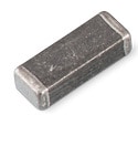 | SPECWE-MPSB EMI Multilayer Power Suppression Bead, –, – | Verfügbarkeit – | Status Aktivi| Produktion ist aktiv. Erwartete Lebenszeit: >10 Jahre. | ProduktserieWE-MPSB EMI Multilayer Power Suppression Bead | – | – | – | Bauform0603 | Betriebstemperatur -55 °C up to +125 °C | – | – | Länge1.6 mm | Breite0.8 mm | Pad Dimension0.3 mm | – | – | – | – | – | – | – | MontageartSMT | – | – | Impedanz @ 100 MHz26 Ω | Maximale Impedanz39 Ω | Maximale Impedanz515 MHz | Nennstrom6500 mA | Impedanz @ 1 GHz33 Ω | Höhe0.8 mm | TypHochstrom | –Verfügbarkeit prüfen | ||||||||||||||||||||||||||||||||||||||||||||||||||||||||||||||||||||||||||||||||||||||||||||||||||||||||||||||||||||||||||||||||||||||||||||||||||||||||||||||||||||||||||||||||||||||||||||||||||||||||||||||||||||||||||||||||||||||||||||||||||||||||||||||||||||||||||||||||||||||||||||||||||||||||||||||||||||||||||||||||||||||||||||||||||||||||||||||||||||||||||||||||||||||||||||||||||||||||||||||||||||||||||||||||||||||||||||||||||||||||||||||||||||||||||||||||||||||||||||||||||||||||||||||||||||||||||||||||||||||||||||||||||||||||||||||||||||||||||||||||||||||||||||||||||||||||||||||||||||||||||||||||||||||||||||||||||||||||||||||||||||||||||||||||||||||||||||||||||||||||||||||||||||||||||||||||||||||||||||||||||||||||||||||||||||||||||||||||||||||||||||||||||||||||||||||||||||||||||||||||||||||||||||||||||||||||||||||||||||||||||||||||||||||||||||||||||||||||||||||||||||||||||||||||||||||||||||||||||||||||||||||||||||||||||||||||||||||||||||||||||||||
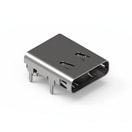 | SPECWR-USB Type C Connectors, –, – Anstehende PCNAufgrund einer anstehenden PCN wird in Kürze eine Änderung am Bauteil durchgeführt. Anbei finden Sie die entsprechende PCN. Bei weiteren Fragen wenden Sie sich bitte an Ihren Vertriebsmitarbeiter. | Simulation– | Verfügbarkeit – | Downloads7 Dateien | Status Aktivi| Produktion ist aktiv. Erwartete Lebenszeit: >10 Jahre. | ProduktserieWR-USB Type C Connectors | – | – | – | – | Betriebstemperatur -40 °C up to +105 °C | Isolationswiderstand1000 MΩ | – | – | – | – | VerpackungTape and Reel | – | – | AnwendungUSB 3.1 | Interface typType C | GenderBuchse | Pins24 | MontageartTHR | Leiterplattendicke1.6 mm | Arbeitsspannung48 V (DC) | – | – | – | Nennstrom5000 mA | – | – | TypHorizontal | –Verfügbarkeit prüfen | ||||||||||||||||||||||||||||||||||||||||||||||||||||||||||||||||||||||||||||||||||||||||||||||||||||||||||||||||||||||||||||||||||||||||||||||||||||||||||||||||||||||||||||||||||||||||||||||||||||||||||||||||||||||||||||||||||||||||||||||||||||||||||||||||||||||||||||||||||||||||||||||||||||||||||||||||||||||||||||||||||||||||||||||||||||||||||||||||||||||||||||||||||||||||||||||||||||||||||||||||||||||||||||||||||||||||||||||||||||||||||||||||||||||||||||||||||||||||||||||||||||||||||||||||||||||||||||||||||||||||||||||||||||||||||||||||||||||||||||||||||||||||||||||||||||||||||||||||||||||||||||||||||||||||||||||||||||||||||||||||||||||||||||||||||||||||||||||||||||||||||||||||||||||||||||||||||||||||||||||||||||||||||||||||||||||||||||||||||||||||||||||||||||||||||||||||||||||||||||||||||||||||||||||||||||||||||||||||||||||||||||||||||||||||||||||||||||||||||||||||||||||||||||||||||||||||||||||||||||||||||||||||||||||||||||||||||||||||||||||||||||
| Erwartete Verfügbarkeit | Eingehender Bestand | Menge |
|---|---|---|
| Aktuelle Verfügbarkeit | – | – |