Power Distribution
Wireless Power Transmission
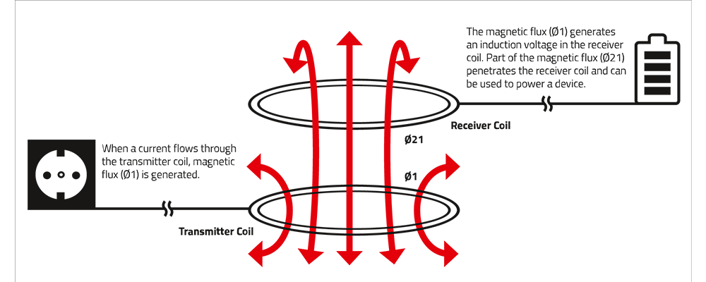
Wireless Power Transmission enables charging devices without the need for apertures or openings in the housing. Disinfection of the device, protection against harsh environments or protection against explosive atmospheres are therefore much easier to achieve.
Aluminium Electrolytic Capacitors
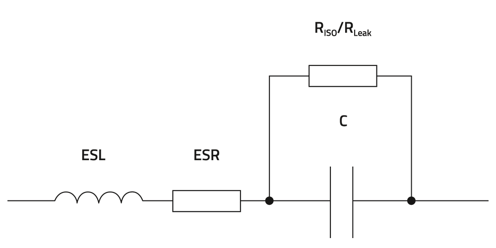
Electrolytic capacitors are the first choice for the input and output bulk capacitors in a DC/DC converter. VVariants such as aluminum polymer or hybrid capacitors offer further advantages such as increased lifetime or lower ESR.
MLCCs - Multilayer Ceramic Chip Capacitors
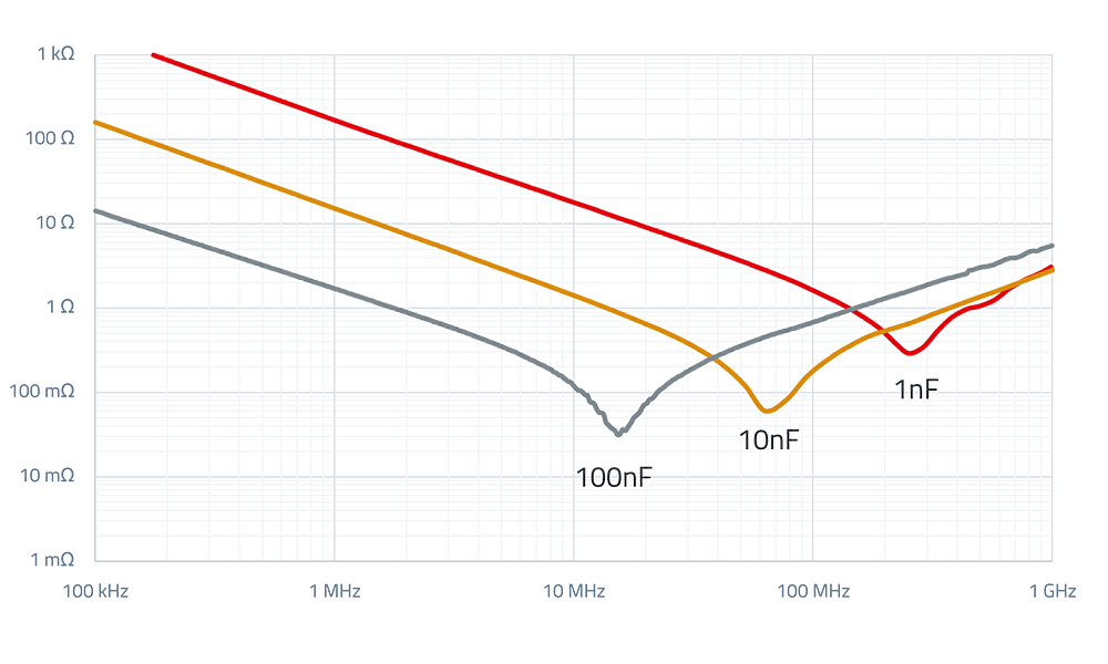
MLCCs are well-suited for filtering the input or output of a DC/DC converter due to their low ESR. Their small size and high capacitance density also make them a viable solution for buffer capacitors in space-constrained applications.
Power Modules
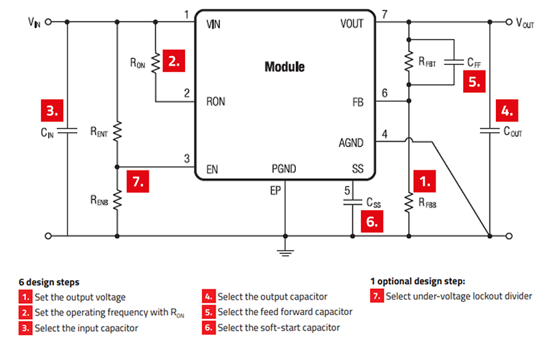
Designing and commissioning a DC/DC converter can be time-consuming. Power modules include many of the typical peripheral components of a DC/DC regulator, thus reducing the BOM count and speeding up the development process.
Power Inductors
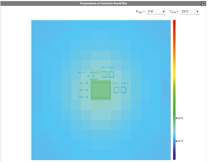
REDEXPERT helps you find the best power inductor for your SMPS and provide useful information regarding efficiency and temperature rise.
Energy Storage (ELDC)
Supercapacitors are easy to use energy storage devices and are in many aspects a bridge between conventional electrolytic capacitors and batteries. They can be charged by any current limited power source, store Energy for a considerable amount of time, and drive electrical applications.
Power Transformer
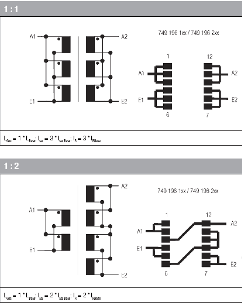
Power transformers provide galvanic isolation and voltage conversion from the primary to the secondary winding. Their design influences efficiency, EMI behaviour, and power density of the DC/DC converter.

Topologies
Short Introduction to Power Distribution
Most microprocessors and ICs require input voltages of 5 V or less, which often does not align with typical supply sources such as AC/DC converters (e.g., 24 V), batteries (with voltage varying by charge state), or energy harvesting sources (well below 1V). DC/DC converters can bridge these differences efficiently. Since switched-mode power supplies (SMPS) generate EMI, proper EMC measures are required to meet standards.
Learn More About Power Distribution
-
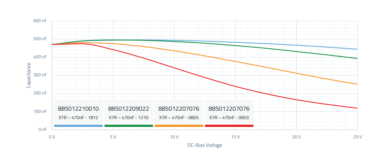
The capacitance of a capacitor is typically also dependent on an applied direct current voltage (DC Bias) and can become significantly lower with increasing voltage. From the DC Bias/capacitance diagram, it is clearly visible that with increasing miniaturization of the component, the nominal value of 470 nF decreases (red curve).
-
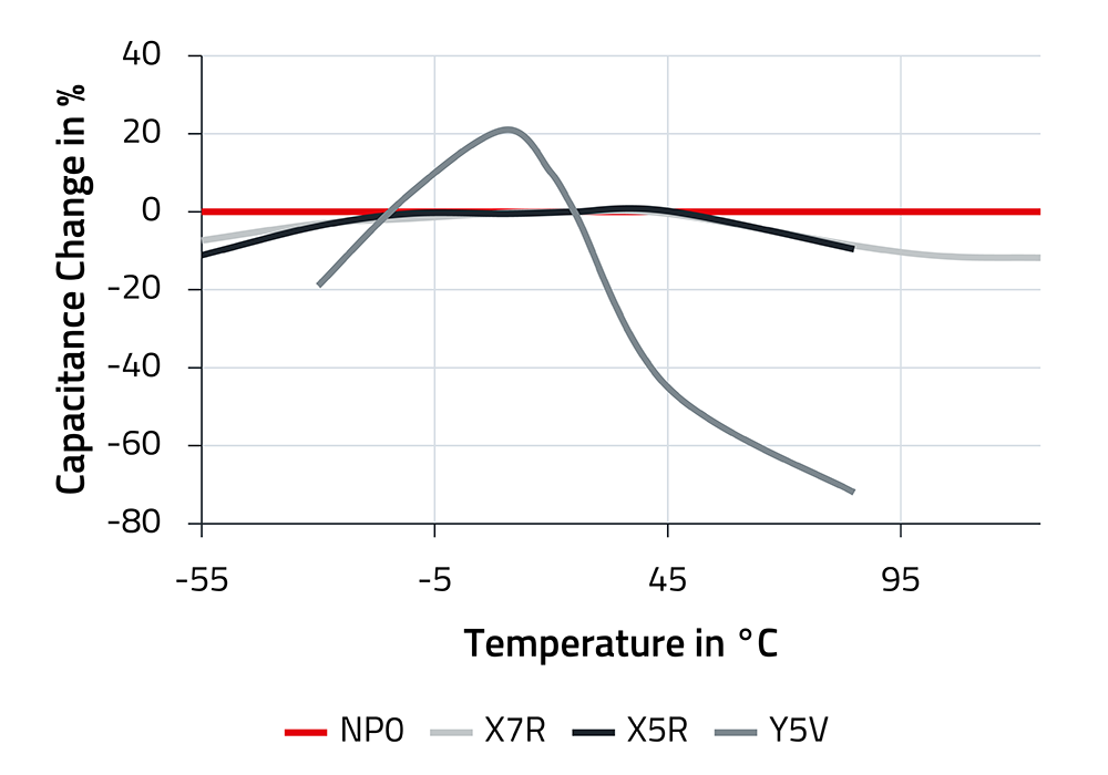
Capacitors should maintain their capacitance as consistently as possible across temperature variations. Three of the materials used, NP0, X7R, and X5R, fulfill this requirement significantly better than Y5V, as can be clearly seen in the diagram. NP0 shows virtually no changes in capacitance over a wide operating temperature range.
-
The lifespan of a capacitor depends on the maximum allowable operating temperature, the ambient temperature, the ripple current, and the applied voltage. The simplified formulas disregard the influence of current and voltage. In RedExpert, the lifespan can be calculated in detail for your application.
-
Flyback and Buck Converter Topologies - Flyback Converter: The energy is stored in the magnetic field of the transformer while the switching element is conducting. Buck Converter: The core is not used for energy storage. Primary and secondary windings conduct simultaneously.
-
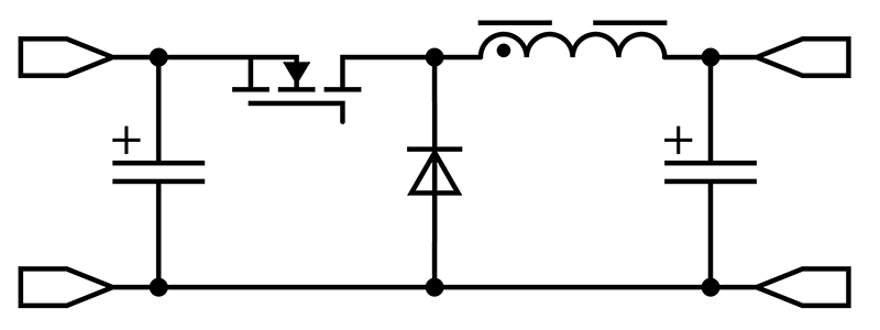
Most power inductors are wound from the inside out, starting with the core. This end of the wire is marked by a dot both in the schematic and on the casing. When the beginning of the winding is connected to the switching node of a switch-mode power supply, the high dV/dt signals are shielded by the outer windings.


