IC-Hersteller (105)
- Alle Hersteller
 Analog Devices
 Infineon Technologies
 Microchip
 Onsemi
 Renesas
 ROHM
ROHM STMicroelectronics
 Texas Instruments
- 3peak incorporated (35)
- Ablic (23)
- Acco Semiconductor (1)
- Advanced Power (4)
- Allegro Microsystems (100)
- Alpha & Omega Semiconductor (37)
- AnalogySemi (3)
- AnDAPT Inc (204)
- Anpec (13)
- AXElite (2)
- Backward (6)
- Bright Power Semiconductor (1)
- Broadcom (46)
- Cambridge GaN Devices (18)
- Chipanalog Micro (10)
- Cologne Chips (1)
- Convenient Power (1)
- Dialog Semiconductor (12)
- Diodes Incorporated (257)
- Divimath (8)
- Elmos AG (1)
- EPC (146)
- e-Peas Semiconductors (1)
- Eta Solutions Co. Ltd. (9)
- GaN Systems (8)
- GaNPower (3)
- Giantec (1)
- Gstek Wuxi (1)
- Helix Semiconductor (7)
- IKON (1)
- Indie Semiconductor (8)
- Innovision Semiconductor Inc (2)
- Intel (68)
- Inventchip Technology (3)
- ISSI (51)
- JoulWatt (20)
- KDPOF (3)
- Kinetic Technology (8)
- Lattice semiconductor Corporation (38)
- Littelfuse (1)
- Lumissil Microsystems (8)
- M3 Technology (M3Tek) (7)
- Macnica (22)
- Marvell Semiconductor (1)
- MaxLinear (181)
- Menlo Micro (1)
- MikroE (25)
- MindCet (2)
- Monolithic Power Systems (982)
- Navitas Semiconductor Inc (6)
- NewEdge Technologies, Inc. (1)
- Nexperia (268)
- Nisshinbo Micro Device Inc. (10)
- Nordic Semiconductor (1)
- Novosense Micro (1)
- NXP (341)
- O2 Micro International Ltd (10)
- On Bright (7)
- Panasonic (2)
- PN Junction Semiconductor (2)
- Power Integrations (117)
- Powermat (1)
- Pulsiv (19)
- Qorvo (99)
- Realsil SuRealsil(tek) Microelectronics (1)
- Richtek (297)
- Sanken Electric Co., Ltd. (16)
- Sckipio (6)
- Semtech (86)
- SG-Micro (58)
- SiFive (2)
- Silanna Semiconductor (9)
- Silergy Corporation (34)
- Silicon Laboratory Inc. (108)
- Silicontent Technology (59)
- Silvertel (59)
- Skycore Semiconductors (1)
- Skyworks (33)
- Southchip (18)
- Summit Wireless (1)
- Tagore Tech (7)
- Taiwan Semiconductor (1)
- TDK Corporation (1)
- Tempo Semiconductor (1)
- Torex (37)
- Toshiba (27)
- Transphorm (21)
- TransSIP (2)
- Union (21)
- uPI Semiconductor (2)
- Valens Semiconductor (31)
- VisIC (1)
- Wise Integration (3)
- Wolfspeed (23)
- Xilinx (22)
- XL Semiconductor (3)
- XYSemi (62)
STMicroelectronics L9963E | Demoboard AEK-POW-BMS63EN
Battery management system module based on L9963E
Details
| Topologie | Battery Management System |
| IC-Revision | 1 |
Beschreibung
The AEK-POW-BMS63EN is a battery management system (BMS) evaluation board that can handle from 1 to 31 Li-ion battery nodes. Each battery node manages from 4 to 14 battery cells, for a voltage range between 48 V and 800 V.The board is based on the L9963E, which is designed for operation in both hybrid (HE) and full electric (BE) vehicles using lithium battery packs, but its use can be extended to other Transportation and Industrial applications.The main activity of the L9963E is monitoring cells and battery node status through stack voltage measurement, cell voltage measurement, temperature measurement, and coulomb counting. Measurement and diagnostic tasks can be executed either on demand or periodically, with a programmable cycle interval. Measurement data are available for an external microcontroller to perform charge balancing and to compute the state of charge (SOC) and the state of health (SOH).The main functions of a standard BMS are monitoring and protecting the battery pack.The monitoring function is related to the measurement of the battery current, voltage, and temperature. The protection function brings the system to a safety state in case of under or overvoltage and overheating.The AEK-POW-BMS63EN provides an elaborate monitoring network to sense the voltage, current, and temperature of each cell. This sensing allows elaborating the SOC of each battery cell and, consequently, the state of charge of all battery packs. The SOC allows assessing the remaining battery capacity, which equates to the remaining driving range.For maintenance reasons, it is important to monitor the SOC estimation over time. According to our algorithm for the SOC calculation, the more the SOC differs from its nominal value (that is, its value when the batteries are new), the more a cell of the battery pack risks over-discharge. Thus, the SOC evolution over time allows asserting the state of health (SOH) of a cell or a battery pack to spot early indications that a cell is at risk of over-discharge or overcharging.The SOC of a battery cell is required to maintain its safe operation and duration during charge, discharge, and storage. However, SOC cannot be measured directly and is estimated from other measurements and known parameters (such as characterization curves or look-up tables). This information on the battery cells is necessary to determine how the voltage varies according to the current, the temperature, etc., on the basis of the battery chemical composition and production lot used.The AEK-POW-BMS63EN can work in two different daisy chain topologies: centralized and dual access ring.In a centralized daisy chain configuration, a series of BMS is connected to an MCU board through a single transceiver connected to the AEK-POW-BMS63EN isolated ISOLport. The BMS are connected to each other through the isolated ISOH port.The MCU communicates with the AEK-COM-ISOSPI1 hosted L9963T transceiver through the SPI protocol. The transceiver converts these signals into ISO SPI signals to communicate with the BMS.The AEK-COM-ISOSPI1 allows converting SPI signals in isolated SPI signals, thereby reducing the number of necessary wires from 4 to 2 and implementing differential communication for higher noise immunity.A dual access ring configuration is also possible by adding another transceiver that makes the communication bidirectional. The secondary ring is used as a backup in case the primary ring fails. Data moves in opposite directions around the rings, and each ring remains independent of the other unless the primary ring fails. The two rings are connected to continue the flow of data traffic.In AutoDevKit ecosystem software package, we created two example demos (one for centralized and one for dual access ring configuration) to elaborate SOC and SOH, using Li-ion batteries. Battery packs may have different SOCs, and balancing is necessary to bring them all to the same charge level. After detecting the lowest charge in the battery pack, all the other battery nodes are discharged to reach its level. The demos explain how to activate the internal MOSFETs of the L9963E, which short-circuit the cell on an external dissipation resistor to discharge it. Passive cell balancing can be performed either via the L9963E internal MOSFETs or via external MOSFETs/resistors. The controller can either manually control the balancing drivers or start a balancing task with a fixed duration. In the second case called silent mode, the balancing may be programmed to continue even when the IC enters a low power mode, to avoid unnecessary current absorption from the battery pack. The balancing function is necessary to lengthen the battery capacity and its duration.Different MCUs can be used. In our demos we used the AEK-MCU-C4MLIT1, while other ASIL-B and ASIL-D microcontrollers of the SPC58 Chorus family are supported.
Typische Anwendungen
- Battery Management System (BMS)
- Battery Management System (BMS) for Electro mobility
Weiterführende Informationen
Artikeldaten
Artikel Nr. | Datenblatt | Simulation | Downloads | Status | Produktserie | λDom typ.(nm) | Emittierte Farbe | λPeak typ.(nm) | IV typ.(mcd) | VF typ.(V) | Chiptechnologie | 2θ50% typ.(°) | Gender | Pins | Typ | Wire Section | Kontaktbeschichtung | IR(A) | Arbeitsspannung(V (AC)) | Kontaktwiderstand(mΩ) | Verpackung | VPE(pcs) | Stranded Wire Section (AWG) | Stranded Wire Section (Metric) | C | Tol. C | VR(V (DC)) | Bauform | Betriebstemperatur | Q | DF(%) | RISO | Keramiktyp | L(mm) | B(mm) | H(mm) | Fl(mm) | Schlüsselweite(mm) | Ti | Brennbarkeitsklasse | Anwendung | Interface typ | Montageart | Leiterplattendicke(mm) | Farbe | Polarität | IR 1(A) | PCB/Kabel/Panel | MusterVerfügbarkeit & Muster | |||||||||||||||||||||||||||||||||||||||||||||||||||||||||||||||||||||||||||||||||||||||||||||||||||||||||||||||||||||||||||||||||||||||||||||||||||||||||||||||||||||||||||||||||||||||||||||||||||||||||||||||||||||||||||||||||||||||||||||||||||||||||||||||||||||||||||||||||||||||||||||||||||||||||||||||||||||||||||||||||||||||||||||||||||||||||||||||||||||||||||||||||||||||||||||||||||||||||||||||||||||||||||||||||||||||||||||||||||||||||||||||||||||||||||||||||||||||||||||||||||||||||||||||||||||||||||||||||||||||||||||||||||||||||||||||||||||||||||||||||||||||||||||||||||||||||||||||||||||||||||||||||||||||||||||||||||||||||||||||||||||||||||||||||||||||||||||||||||||||||||||||||||||||||||||||||||||||||||||||||||||||||||||||||||||||||||||||||||||||||||||||||||||||||||||||||||||||||||||||||||||||||||||||||||||||||||||||||||||||||||||||||||||||||||||||||||||||||||||||||||||||||||||||||||||||||||||||||||||||||||||||||||||||||||||||||||||
|---|---|---|---|---|---|---|---|---|---|---|---|---|---|---|---|---|---|---|---|---|---|---|---|---|---|---|---|---|---|---|---|---|---|---|---|---|---|---|---|---|---|---|---|---|---|---|---|---|---|---|---|---|---|---|---|---|---|---|---|---|---|---|---|---|---|---|---|---|---|---|---|---|---|---|---|---|---|---|---|---|---|---|---|---|---|---|---|---|---|---|---|---|---|---|---|---|---|---|---|---|---|---|---|---|---|---|---|---|---|---|---|---|---|---|---|---|---|---|---|---|---|---|---|---|---|---|---|---|---|---|---|---|---|---|---|---|---|---|---|---|---|---|---|---|---|---|---|---|---|---|---|---|---|---|---|---|---|---|---|---|---|---|---|---|---|---|---|---|---|---|---|---|---|---|---|---|---|---|---|---|---|---|---|---|---|---|---|---|---|---|---|---|---|---|---|---|---|---|---|---|---|---|---|---|---|---|---|---|---|---|---|---|---|---|---|---|---|---|---|---|---|---|---|---|---|---|---|---|---|---|---|---|---|---|---|---|---|---|---|---|---|---|---|---|---|---|---|---|---|---|---|---|---|---|---|---|---|---|---|---|---|---|---|---|---|---|---|---|---|---|---|---|---|---|---|---|---|---|---|---|---|---|---|---|---|---|---|---|---|---|---|---|---|---|---|---|---|---|---|---|---|---|---|---|---|---|---|---|---|---|---|---|---|---|---|---|---|---|---|---|---|---|---|---|---|---|---|---|---|---|---|---|---|---|---|---|---|---|---|---|---|---|---|---|---|---|---|---|---|---|---|---|---|---|---|---|---|---|---|---|---|---|---|---|---|---|---|---|---|---|---|---|---|---|---|---|---|---|---|---|---|---|---|---|---|---|---|---|---|---|---|---|---|---|---|---|---|---|---|---|---|---|---|---|---|---|---|---|---|---|---|---|---|---|---|---|---|---|---|---|---|---|---|---|---|---|---|---|---|---|---|---|---|---|---|---|---|---|---|---|---|---|---|---|---|---|---|---|---|---|---|---|---|---|---|---|---|---|---|---|---|---|---|---|---|---|---|---|---|---|---|---|---|---|---|---|---|---|---|---|---|---|---|---|---|---|---|---|---|---|---|---|---|---|---|---|---|---|---|---|---|---|---|---|---|---|---|---|---|---|---|---|---|---|---|---|---|---|---|---|---|---|---|---|---|---|---|---|---|---|---|---|---|---|---|---|---|---|---|---|---|---|---|---|---|---|---|---|---|---|---|---|---|---|---|---|---|---|---|---|---|---|---|---|---|---|---|---|---|---|---|---|---|---|---|---|---|---|---|---|---|---|---|---|---|---|---|---|---|---|---|---|---|---|---|---|---|---|---|---|---|---|---|---|---|---|---|---|---|---|---|---|---|---|---|---|---|---|---|---|---|---|---|---|---|---|---|---|---|---|---|---|---|---|---|---|---|---|---|---|---|---|---|---|---|---|---|---|---|---|---|---|---|---|---|---|---|---|---|---|---|---|---|---|---|---|---|---|---|---|---|---|---|---|---|---|---|---|---|---|---|---|---|---|---|---|---|---|---|---|---|---|---|---|---|---|---|---|---|---|---|---|---|---|---|---|---|---|---|---|---|---|---|---|---|---|---|---|---|---|---|---|---|---|---|---|---|---|---|---|---|---|---|---|---|---|---|---|---|---|---|---|---|---|---|---|---|---|---|---|---|---|---|---|---|---|---|---|---|---|---|---|---|---|---|---|---|---|---|---|---|---|---|---|---|---|---|---|---|---|---|---|---|---|---|---|---|---|---|---|---|---|---|---|---|---|---|---|---|---|---|---|---|---|---|---|---|---|---|---|---|---|---|---|---|---|---|---|---|---|---|---|---|---|---|---|---|---|---|---|---|---|---|---|---|---|---|---|---|---|---|---|---|---|---|---|---|---|---|---|---|---|---|---|---|---|---|---|---|---|---|---|---|---|---|---|---|---|---|---|---|---|---|---|---|---|---|---|---|---|---|---|---|---|---|---|---|---|---|---|---|---|---|---|---|---|---|---|---|---|---|---|---|---|---|---|---|---|---|---|---|---|---|---|---|---|---|---|---|---|---|---|---|---|---|---|---|---|---|---|---|---|---|---|---|---|---|---|---|---|---|---|---|---|---|---|---|---|---|---|---|---|---|---|---|---|---|---|---|---|---|---|---|---|---|---|---|---|---|---|---|---|---|---|---|---|---|---|---|---|---|---|---|---|---|---|---|---|---|---|---|---|---|---|---|---|---|---|
| Jetzt einloggen, um Verfügbarkeiten zu sehen und Verfügbarkeitsprognosen anzufragen. LOGIN | ||||||||||||||||||||||||||||||||||||||||||||||||||||||||||||||||||||||||||||||||||||||||||||||||||||||||||||||||||||||||||||||||||||||||||||||||||||||||||||||||||||||||||||||||||||||||||||||||||||||||||||||||||||||||||||||||||||||||||||||||||||||||||||||||||||||||||||||||||||||||||||||||||||||||||||||||||||||||||||||||||||||||||||||||||||||||||||||||||||||||||||||||||||||||||||||||||||||||||||||||||||||||||||||||||||||||||||||||||||||||||||||||||||||||||||||||||||||||||||||||||||||||||||||||||||||||||||||||||||||||||||||||||||||||||||||||||||||||||||||||||||||||||||||||||||||||||||||||||||||||||||||||||||||||||||||||||||||||||||||||||||||||||||||||||||||||||||||||||||||||||||||||||||||||||||||||||||||||||||||||||||||||||||||||||||||||||||||||||||||||||||||||||||||||||||||||||||||||||||||||||||||||||||||||||||||||||||||||||||||||||||||||||||||||||||||||||||||||||||||||||||||||||||||||||||||||||||||||||||||||||||||||||||||||||||||||||||||||||||||||||||||||||||||||||||||||||||||||||||||
 | SPECWL-SMCW SMT Mono-color Chip LED Waterclear, 525 nm, Grün | Verfügbarkeit – | Status Aktivi| Produktion ist aktiv. Erwartete Lebenszeit: >10 Jahre. | ProduktserieWL-SMCW SMT Mono-color Chip LED Waterclear | dominante Wellenlänge [typ.]525 nm | Emittierte FarbeGrün | Spitzen-Wellenlänge [typ.]515 nm | Lichtstärke [typ.]450 mcd | Durchlassspannung [typ.]3.2 V | ChiptechnologieInGaN | Abstrahlwinkel Phi 0° [typ.]140 ° | – | – | – | – | – | – | – | – | VerpackungTape and Reel | Verpackungseinheit4000 pcs | – | – | – | – | – | Bauform0805 | Betriebstemperatur -40 °C up to +85 °C | – | – | – | – | Länge2 mm | Breite1.25 mm | Höhe0.7 mm | – | – | – | – | – | – | MontageartSMT | – | – | – | – | – | –Verfügbarkeit prüfen | ||||||||||||||||||||||||||||||||||||||||||||||||||||||||||||||||||||||||||||||||||||||||||||||||||||||||||||||||||||||||||||||||||||||||||||||||||||||||||||||||||||||||||||||||||||||||||||||||||||||||||||||||||||||||||||||||||||||||||||||||||||||||||||||||||||||||||||||||||||||||||||||||||||||||||||||||||||||||||||||||||||||||||||||||||||||||||||||||||||||||||||||||||||||||||||||||||||||||||||||||||||||||||||||||||||||||||||||||||||||||||||||||||||||||||||||||||||||||||||||||||||||||||||||||||||||||||||||||||||||||||||||||||||||||||||||||||||||||||||||||||||||||||||||||||||||||||||||||||||||||||||||||||||||||||||||||||||||||||||||||||||||||||||||||||||||||||||||||||||||||||||||||||||||||||||||||||||||||||||||||||||||||||||||||||||||||||||||||||||||||||||||||||||||||||||||||||||||||||||||||||||||||||||||||||||||||||||||||||||||||||||||||||||||||||||||||||||||||||||||||||||||||||||||||||||||||||||||||||||||||||||||||||||||||||||||||||||||
SPECWCAP-CSGP MLCCs 50 V(DC), –, – | Verfügbarkeit – | Status Aktivi| Produktion ist aktiv. Erwartete Lebenszeit: >10 Jahre. | ProduktserieWCAP-CSGP MLCCs 50 V(DC) | – | – | – | – | – | – | – | – | – | – | – | – | – | – | – | Verpackung7" Tape & Reel | Verpackungseinheit4000 pcs | – | – | Kapazität22 pF | Kapazität±5% | Nennspannung50 V (DC) | Bauform0603 | Betriebstemperatur -55 °C up to +125 °C | Güte840 | – | Isolationswiderstand10 GΩ | KeramiktypNP0 Klasse I | Länge1.6 mm | Breite0.8 mm | Höhe0.8 mm | Pad Dimension0.4 mm | – | – | – | – | – | – | – | – | – | – | – | –Verfügbarkeit prüfen | |||||||||||||||||||||||||||||||||||||||||||||||||||||||||||||||||||||||||||||||||||||||||||||||||||||||||||||||||||||||||||||||||||||||||||||||||||||||||||||||||||||||||||||||||||||||||||||||||||||||||||||||||||||||||||||||||||||||||||||||||||||||||||||||||||||||||||||||||||||||||||||||||||||||||||||||||||||||||||||||||||||||||||||||||||||||||||||||||||||||||||||||||||||||||||||||||||||||||||||||||||||||||||||||||||||||||||||||||||||||||||||||||||||||||||||||||||||||||||||||||||||||||||||||||||||||||||||||||||||||||||||||||||||||||||||||||||||||||||||||||||||||||||||||||||||||||||||||||||||||||||||||||||||||||||||||||||||||||||||||||||||||||||||||||||||||||||||||||||||||||||||||||||||||||||||||||||||||||||||||||||||||||||||||||||||||||||||||||||||||||||||||||||||||||||||||||||||||||||||||||||||||||||||||||||||||||||||||||||||||||||||||||||||||||||||||||||||||||||||||||||||||||||||||||||||||||||||||||||||||||||||||||||||||||||||||||||||||
SPECWCAP-CSGP MLCCs 50 V(DC), –, – | Verfügbarkeit – | Status Aktivi| Produktion ist aktiv. Erwartete Lebenszeit: >10 Jahre. | ProduktserieWCAP-CSGP MLCCs 50 V(DC) | – | – | – | – | – | – | – | – | – | – | – | – | – | – | – | Verpackung7" Tape & Reel | Verpackungseinheit4000 pcs | – | – | Kapazität33 pF | Kapazität±5% | Nennspannung50 V (DC) | Bauform0603 | Betriebstemperatur -55 °C up to +125 °C | Güte1000 | – | Isolationswiderstand10 GΩ | KeramiktypNP0 Klasse I | Länge1.6 mm | Breite0.8 mm | Höhe0.8 mm | Pad Dimension0.4 mm | – | – | – | – | – | – | – | – | – | – | – | –Verfügbarkeit prüfen | |||||||||||||||||||||||||||||||||||||||||||||||||||||||||||||||||||||||||||||||||||||||||||||||||||||||||||||||||||||||||||||||||||||||||||||||||||||||||||||||||||||||||||||||||||||||||||||||||||||||||||||||||||||||||||||||||||||||||||||||||||||||||||||||||||||||||||||||||||||||||||||||||||||||||||||||||||||||||||||||||||||||||||||||||||||||||||||||||||||||||||||||||||||||||||||||||||||||||||||||||||||||||||||||||||||||||||||||||||||||||||||||||||||||||||||||||||||||||||||||||||||||||||||||||||||||||||||||||||||||||||||||||||||||||||||||||||||||||||||||||||||||||||||||||||||||||||||||||||||||||||||||||||||||||||||||||||||||||||||||||||||||||||||||||||||||||||||||||||||||||||||||||||||||||||||||||||||||||||||||||||||||||||||||||||||||||||||||||||||||||||||||||||||||||||||||||||||||||||||||||||||||||||||||||||||||||||||||||||||||||||||||||||||||||||||||||||||||||||||||||||||||||||||||||||||||||||||||||||||||||||||||||||||||||||||||||||||||
SPECWCAP-CSGP MLCCs 50 V(DC), –, – | Verfügbarkeit – | Status Aktivi| Produktion ist aktiv. Erwartete Lebenszeit: >10 Jahre. | ProduktserieWCAP-CSGP MLCCs 50 V(DC) | – | – | – | – | – | – | – | – | – | – | – | – | – | – | – | Verpackung7" Tape & Reel | Verpackungseinheit4000 pcs | – | – | Kapazität2.2 nF | Kapazität±10% | Nennspannung50 V (DC) | Bauform0603 | Betriebstemperatur -55 °C up to +125 °C | – | Verlustfaktor2.5 % | Isolationswiderstand10 GΩ | KeramiktypX7R Klasse II | Länge1.6 mm | Breite0.8 mm | Höhe0.8 mm | Pad Dimension0.4 mm | – | – | – | – | – | – | – | – | – | – | – | –Verfügbarkeit prüfen | |||||||||||||||||||||||||||||||||||||||||||||||||||||||||||||||||||||||||||||||||||||||||||||||||||||||||||||||||||||||||||||||||||||||||||||||||||||||||||||||||||||||||||||||||||||||||||||||||||||||||||||||||||||||||||||||||||||||||||||||||||||||||||||||||||||||||||||||||||||||||||||||||||||||||||||||||||||||||||||||||||||||||||||||||||||||||||||||||||||||||||||||||||||||||||||||||||||||||||||||||||||||||||||||||||||||||||||||||||||||||||||||||||||||||||||||||||||||||||||||||||||||||||||||||||||||||||||||||||||||||||||||||||||||||||||||||||||||||||||||||||||||||||||||||||||||||||||||||||||||||||||||||||||||||||||||||||||||||||||||||||||||||||||||||||||||||||||||||||||||||||||||||||||||||||||||||||||||||||||||||||||||||||||||||||||||||||||||||||||||||||||||||||||||||||||||||||||||||||||||||||||||||||||||||||||||||||||||||||||||||||||||||||||||||||||||||||||||||||||||||||||||||||||||||||||||||||||||||||||||||||||||||||||||||||||||||||||||
SPECWCAP-CSGP MLCCs 50 V(DC), –, – | Verfügbarkeit – | Status Aktivi| Produktion ist aktiv. Erwartete Lebenszeit: >10 Jahre. | ProduktserieWCAP-CSGP MLCCs 50 V(DC) | – | – | – | – | – | – | – | – | – | – | – | – | – | – | – | Verpackung7" Tape & Reel | Verpackungseinheit4000 pcs | – | – | Kapazität4.7 nF | Kapazität±10% | Nennspannung50 V (DC) | Bauform0603 | Betriebstemperatur -55 °C up to +125 °C | – | Verlustfaktor2.5 % | Isolationswiderstand10 GΩ | KeramiktypX7R Klasse II | Länge1.6 mm | Breite0.8 mm | Höhe0.8 mm | Pad Dimension0.4 mm | – | – | – | – | – | – | – | – | – | – | – | –Verfügbarkeit prüfen | |||||||||||||||||||||||||||||||||||||||||||||||||||||||||||||||||||||||||||||||||||||||||||||||||||||||||||||||||||||||||||||||||||||||||||||||||||||||||||||||||||||||||||||||||||||||||||||||||||||||||||||||||||||||||||||||||||||||||||||||||||||||||||||||||||||||||||||||||||||||||||||||||||||||||||||||||||||||||||||||||||||||||||||||||||||||||||||||||||||||||||||||||||||||||||||||||||||||||||||||||||||||||||||||||||||||||||||||||||||||||||||||||||||||||||||||||||||||||||||||||||||||||||||||||||||||||||||||||||||||||||||||||||||||||||||||||||||||||||||||||||||||||||||||||||||||||||||||||||||||||||||||||||||||||||||||||||||||||||||||||||||||||||||||||||||||||||||||||||||||||||||||||||||||||||||||||||||||||||||||||||||||||||||||||||||||||||||||||||||||||||||||||||||||||||||||||||||||||||||||||||||||||||||||||||||||||||||||||||||||||||||||||||||||||||||||||||||||||||||||||||||||||||||||||||||||||||||||||||||||||||||||||||||||||||||||||||||||
SPECWCAP-CSGP MLCCs 50 V(DC), –, – | Verfügbarkeit – | Status Aktivi| Produktion ist aktiv. Erwartete Lebenszeit: >10 Jahre. | ProduktserieWCAP-CSGP MLCCs 50 V(DC) | – | – | – | – | – | – | – | – | – | – | – | – | – | – | – | Verpackung7" Tape & Reel | Verpackungseinheit4000 pcs | – | – | Kapazität6.8 nF | Kapazität±10% | Nennspannung50 V (DC) | Bauform0603 | Betriebstemperatur -55 °C up to +125 °C | – | Verlustfaktor2.5 % | Isolationswiderstand10 GΩ | KeramiktypX7R Klasse II | Länge1.6 mm | Breite0.8 mm | Höhe0.8 mm | Pad Dimension0.4 mm | – | – | – | – | – | – | – | – | – | – | – | –Verfügbarkeit prüfen | |||||||||||||||||||||||||||||||||||||||||||||||||||||||||||||||||||||||||||||||||||||||||||||||||||||||||||||||||||||||||||||||||||||||||||||||||||||||||||||||||||||||||||||||||||||||||||||||||||||||||||||||||||||||||||||||||||||||||||||||||||||||||||||||||||||||||||||||||||||||||||||||||||||||||||||||||||||||||||||||||||||||||||||||||||||||||||||||||||||||||||||||||||||||||||||||||||||||||||||||||||||||||||||||||||||||||||||||||||||||||||||||||||||||||||||||||||||||||||||||||||||||||||||||||||||||||||||||||||||||||||||||||||||||||||||||||||||||||||||||||||||||||||||||||||||||||||||||||||||||||||||||||||||||||||||||||||||||||||||||||||||||||||||||||||||||||||||||||||||||||||||||||||||||||||||||||||||||||||||||||||||||||||||||||||||||||||||||||||||||||||||||||||||||||||||||||||||||||||||||||||||||||||||||||||||||||||||||||||||||||||||||||||||||||||||||||||||||||||||||||||||||||||||||||||||||||||||||||||||||||||||||||||||||||||||||||||||||
SPECWCAP-CSGP MLCCs 50 V(DC), –, – | Verfügbarkeit – | Status Aktivi| Produktion ist aktiv. Erwartete Lebenszeit: >10 Jahre. | ProduktserieWCAP-CSGP MLCCs 50 V(DC) | – | – | – | – | – | – | – | – | – | – | – | – | – | – | – | Verpackung7" Tape & Reel | Verpackungseinheit4000 pcs | – | – | Kapazität10 nF | Kapazität±10% | Nennspannung50 V (DC) | Bauform0603 | Betriebstemperatur -55 °C up to +125 °C | – | Verlustfaktor2.5 % | Isolationswiderstand10 GΩ | KeramiktypX7R Klasse II | Länge1.6 mm | Breite0.8 mm | Höhe0.8 mm | Pad Dimension0.4 mm | – | – | – | – | – | – | – | – | – | – | – | –Verfügbarkeit prüfen | |||||||||||||||||||||||||||||||||||||||||||||||||||||||||||||||||||||||||||||||||||||||||||||||||||||||||||||||||||||||||||||||||||||||||||||||||||||||||||||||||||||||||||||||||||||||||||||||||||||||||||||||||||||||||||||||||||||||||||||||||||||||||||||||||||||||||||||||||||||||||||||||||||||||||||||||||||||||||||||||||||||||||||||||||||||||||||||||||||||||||||||||||||||||||||||||||||||||||||||||||||||||||||||||||||||||||||||||||||||||||||||||||||||||||||||||||||||||||||||||||||||||||||||||||||||||||||||||||||||||||||||||||||||||||||||||||||||||||||||||||||||||||||||||||||||||||||||||||||||||||||||||||||||||||||||||||||||||||||||||||||||||||||||||||||||||||||||||||||||||||||||||||||||||||||||||||||||||||||||||||||||||||||||||||||||||||||||||||||||||||||||||||||||||||||||||||||||||||||||||||||||||||||||||||||||||||||||||||||||||||||||||||||||||||||||||||||||||||||||||||||||||||||||||||||||||||||||||||||||||||||||||||||||||||||||||||||||||
SPECWCAP-CSGP MLCCs 50 V(DC), –, – | Verfügbarkeit – | Status Aktivi| Produktion ist aktiv. Erwartete Lebenszeit: >10 Jahre. | ProduktserieWCAP-CSGP MLCCs 50 V(DC) | – | – | – | – | – | – | – | – | – | – | – | – | – | – | – | Verpackung7" Tape & Reel | Verpackungseinheit4000 pcs | – | – | Kapazität47 nF | Kapazität±10% | Nennspannung50 V (DC) | Bauform0603 | Betriebstemperatur -55 °C up to +125 °C | – | Verlustfaktor3 % | Isolationswiderstand10 GΩ | KeramiktypX7R Klasse II | Länge1.6 mm | Breite0.8 mm | Höhe0.8 mm | Pad Dimension0.4 mm | – | – | – | – | – | – | – | – | – | – | – | –Verfügbarkeit prüfen | |||||||||||||||||||||||||||||||||||||||||||||||||||||||||||||||||||||||||||||||||||||||||||||||||||||||||||||||||||||||||||||||||||||||||||||||||||||||||||||||||||||||||||||||||||||||||||||||||||||||||||||||||||||||||||||||||||||||||||||||||||||||||||||||||||||||||||||||||||||||||||||||||||||||||||||||||||||||||||||||||||||||||||||||||||||||||||||||||||||||||||||||||||||||||||||||||||||||||||||||||||||||||||||||||||||||||||||||||||||||||||||||||||||||||||||||||||||||||||||||||||||||||||||||||||||||||||||||||||||||||||||||||||||||||||||||||||||||||||||||||||||||||||||||||||||||||||||||||||||||||||||||||||||||||||||||||||||||||||||||||||||||||||||||||||||||||||||||||||||||||||||||||||||||||||||||||||||||||||||||||||||||||||||||||||||||||||||||||||||||||||||||||||||||||||||||||||||||||||||||||||||||||||||||||||||||||||||||||||||||||||||||||||||||||||||||||||||||||||||||||||||||||||||||||||||||||||||||||||||||||||||||||||||||||||||||||||||||
SPECWCAP-CSGP MLCCs 50 V(DC), –, – | Verfügbarkeit – | Status Aktivi| Produktion ist aktiv. Erwartete Lebenszeit: >10 Jahre. | ProduktserieWCAP-CSGP MLCCs 50 V(DC) | – | – | – | – | – | – | – | – | – | – | – | – | – | – | – | Verpackung7" Tape & Reel | Verpackungseinheit4000 pcs | – | – | Kapazität68 nF | Kapazität±10% | Nennspannung50 V (DC) | Bauform0603 | Betriebstemperatur -55 °C up to +125 °C | – | Verlustfaktor3 % | Isolationswiderstand7.4 GΩ | KeramiktypX7R Klasse II | Länge1.6 mm | Breite0.8 mm | Höhe0.8 mm | Pad Dimension0.4 mm | – | – | – | – | – | – | – | – | – | – | – | –Verfügbarkeit prüfen | |||||||||||||||||||||||||||||||||||||||||||||||||||||||||||||||||||||||||||||||||||||||||||||||||||||||||||||||||||||||||||||||||||||||||||||||||||||||||||||||||||||||||||||||||||||||||||||||||||||||||||||||||||||||||||||||||||||||||||||||||||||||||||||||||||||||||||||||||||||||||||||||||||||||||||||||||||||||||||||||||||||||||||||||||||||||||||||||||||||||||||||||||||||||||||||||||||||||||||||||||||||||||||||||||||||||||||||||||||||||||||||||||||||||||||||||||||||||||||||||||||||||||||||||||||||||||||||||||||||||||||||||||||||||||||||||||||||||||||||||||||||||||||||||||||||||||||||||||||||||||||||||||||||||||||||||||||||||||||||||||||||||||||||||||||||||||||||||||||||||||||||||||||||||||||||||||||||||||||||||||||||||||||||||||||||||||||||||||||||||||||||||||||||||||||||||||||||||||||||||||||||||||||||||||||||||||||||||||||||||||||||||||||||||||||||||||||||||||||||||||||||||||||||||||||||||||||||||||||||||||||||||||||||||||||||||||||||||
SPECWCAP-CSGP MLCCs 50 V(DC), –, – | Verfügbarkeit – | Status Aktivi| Produktion ist aktiv. Erwartete Lebenszeit: >10 Jahre. | ProduktserieWCAP-CSGP MLCCs 50 V(DC) | – | – | – | – | – | – | – | – | – | – | – | – | – | – | – | Verpackung7" Tape & Reel | Verpackungseinheit4000 pcs | – | – | Kapazität100 nF | Kapazität±10% | Nennspannung50 V (DC) | Bauform0603 | Betriebstemperatur -55 °C up to +125 °C | – | Verlustfaktor3 % | Isolationswiderstand5 GΩ | KeramiktypX7R Klasse II | Länge1.6 mm | Breite0.8 mm | Höhe0.8 mm | Pad Dimension0.4 mm | – | – | – | – | – | – | – | – | – | – | – | –Verfügbarkeit prüfen | |||||||||||||||||||||||||||||||||||||||||||||||||||||||||||||||||||||||||||||||||||||||||||||||||||||||||||||||||||||||||||||||||||||||||||||||||||||||||||||||||||||||||||||||||||||||||||||||||||||||||||||||||||||||||||||||||||||||||||||||||||||||||||||||||||||||||||||||||||||||||||||||||||||||||||||||||||||||||||||||||||||||||||||||||||||||||||||||||||||||||||||||||||||||||||||||||||||||||||||||||||||||||||||||||||||||||||||||||||||||||||||||||||||||||||||||||||||||||||||||||||||||||||||||||||||||||||||||||||||||||||||||||||||||||||||||||||||||||||||||||||||||||||||||||||||||||||||||||||||||||||||||||||||||||||||||||||||||||||||||||||||||||||||||||||||||||||||||||||||||||||||||||||||||||||||||||||||||||||||||||||||||||||||||||||||||||||||||||||||||||||||||||||||||||||||||||||||||||||||||||||||||||||||||||||||||||||||||||||||||||||||||||||||||||||||||||||||||||||||||||||||||||||||||||||||||||||||||||||||||||||||||||||||||||||||||||||||||
SPECWCAP-CSGP MLCCs 25 V(DC), –, – | Verfügbarkeit – | Status Aktivi| Produktion ist aktiv. Erwartete Lebenszeit: >10 Jahre. | ProduktserieWCAP-CSGP MLCCs 25 V(DC) | – | – | – | – | – | – | – | – | – | – | – | – | – | – | – | Verpackung7" Tape & Reel | Verpackungseinheit3000 pcs | – | – | Kapazität2.2 µF | Kapazität±10% | Nennspannung25 V (DC) | Bauform0805 | Betriebstemperatur -55 °C up to +125 °C | – | Verlustfaktor10 % | Isolationswiderstand0.05 GΩ | KeramiktypX7R Klasse II | Länge2 mm | Breite1.25 mm | Höhe1.25 mm | Pad Dimension0.5 mm | – | – | – | – | – | – | – | – | – | – | – | –Verfügbarkeit prüfen | |||||||||||||||||||||||||||||||||||||||||||||||||||||||||||||||||||||||||||||||||||||||||||||||||||||||||||||||||||||||||||||||||||||||||||||||||||||||||||||||||||||||||||||||||||||||||||||||||||||||||||||||||||||||||||||||||||||||||||||||||||||||||||||||||||||||||||||||||||||||||||||||||||||||||||||||||||||||||||||||||||||||||||||||||||||||||||||||||||||||||||||||||||||||||||||||||||||||||||||||||||||||||||||||||||||||||||||||||||||||||||||||||||||||||||||||||||||||||||||||||||||||||||||||||||||||||||||||||||||||||||||||||||||||||||||||||||||||||||||||||||||||||||||||||||||||||||||||||||||||||||||||||||||||||||||||||||||||||||||||||||||||||||||||||||||||||||||||||||||||||||||||||||||||||||||||||||||||||||||||||||||||||||||||||||||||||||||||||||||||||||||||||||||||||||||||||||||||||||||||||||||||||||||||||||||||||||||||||||||||||||||||||||||||||||||||||||||||||||||||||||||||||||||||||||||||||||||||||||||||||||||||||||||||||||||||||||||||
SPECWCAP-CSGP MLCCs 50 V(DC), –, – | Verfügbarkeit – | Status Aktivi| Produktion ist aktiv. Erwartete Lebenszeit: >10 Jahre. | ProduktserieWCAP-CSGP MLCCs 50 V(DC) | – | – | – | – | – | – | – | – | – | – | – | – | – | – | – | Verpackung7" Tape & Reel | Verpackungseinheit3000 pcs | – | – | Kapazität1 µF | Kapazität±10% | Nennspannung50 V (DC) | Bauform0805 | Betriebstemperatur -55 °C up to +125 °C | – | Verlustfaktor10 % | Isolationswiderstand0.1 GΩ | KeramiktypX7R Klasse II | Länge2 mm | Breite1.25 mm | Höhe1.25 mm | Pad Dimension0.5 mm | – | – | – | – | – | – | – | – | – | – | – | –Verfügbarkeit prüfen | |||||||||||||||||||||||||||||||||||||||||||||||||||||||||||||||||||||||||||||||||||||||||||||||||||||||||||||||||||||||||||||||||||||||||||||||||||||||||||||||||||||||||||||||||||||||||||||||||||||||||||||||||||||||||||||||||||||||||||||||||||||||||||||||||||||||||||||||||||||||||||||||||||||||||||||||||||||||||||||||||||||||||||||||||||||||||||||||||||||||||||||||||||||||||||||||||||||||||||||||||||||||||||||||||||||||||||||||||||||||||||||||||||||||||||||||||||||||||||||||||||||||||||||||||||||||||||||||||||||||||||||||||||||||||||||||||||||||||||||||||||||||||||||||||||||||||||||||||||||||||||||||||||||||||||||||||||||||||||||||||||||||||||||||||||||||||||||||||||||||||||||||||||||||||||||||||||||||||||||||||||||||||||||||||||||||||||||||||||||||||||||||||||||||||||||||||||||||||||||||||||||||||||||||||||||||||||||||||||||||||||||||||||||||||||||||||||||||||||||||||||||||||||||||||||||||||||||||||||||||||||||||||||||||||||||||||||||||
SPECWCAP-CSGP MLCCs 50 V(DC), –, – | Verfügbarkeit – | Status Aktivi| Produktion ist aktiv. Erwartete Lebenszeit: >10 Jahre. | ProduktserieWCAP-CSGP MLCCs 50 V(DC) | – | – | – | – | – | – | – | – | – | – | – | – | – | – | – | Verpackung7" Tape & Reel | Verpackungseinheit2000 pcs | – | – | Kapazität4.7 µF | Kapazität±10% | Nennspannung50 V (DC) | Bauform1206 | Betriebstemperatur -55 °C up to +125 °C | – | Verlustfaktor10 % | Isolationswiderstand0.02 GΩ | KeramiktypX7R Klasse II | Länge3.2 mm | Breite1.6 mm | Höhe1.6 mm | Pad Dimension0.5 mm | – | – | – | – | – | – | – | – | – | – | – | –Verfügbarkeit prüfen | |||||||||||||||||||||||||||||||||||||||||||||||||||||||||||||||||||||||||||||||||||||||||||||||||||||||||||||||||||||||||||||||||||||||||||||||||||||||||||||||||||||||||||||||||||||||||||||||||||||||||||||||||||||||||||||||||||||||||||||||||||||||||||||||||||||||||||||||||||||||||||||||||||||||||||||||||||||||||||||||||||||||||||||||||||||||||||||||||||||||||||||||||||||||||||||||||||||||||||||||||||||||||||||||||||||||||||||||||||||||||||||||||||||||||||||||||||||||||||||||||||||||||||||||||||||||||||||||||||||||||||||||||||||||||||||||||||||||||||||||||||||||||||||||||||||||||||||||||||||||||||||||||||||||||||||||||||||||||||||||||||||||||||||||||||||||||||||||||||||||||||||||||||||||||||||||||||||||||||||||||||||||||||||||||||||||||||||||||||||||||||||||||||||||||||||||||||||||||||||||||||||||||||||||||||||||||||||||||||||||||||||||||||||||||||||||||||||||||||||||||||||||||||||||||||||||||||||||||||||||||||||||||||||||||||||||||||||||
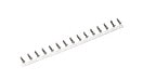
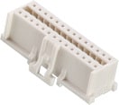 | SPECWR-WTB 2.00 mm Female Dual Row Terminal Housing w. positive locking, –, – | Simulation– | Verfügbarkeit – | Status Aktivi| Produktion ist aktiv. Erwartete Lebenszeit: >10 Jahre. | – | – | – | – | – | – | – | GenderWeiblich | Pins30 | TypKlemmengehäuse | – | – | Nennstrom3 A | – | – | VerpackungBeutel | – | – | – | – | – | – | – | Betriebstemperatur -25 °C up to +85 °C | – | – | Isolationswiderstand1000 MΩ | – | Länge33.4 mm | – | – | – | – | – | – | – | – | – | – | – | – | – | PCB/Kabel/PanelKabel | –Verfügbarkeit prüfen | ||||||||||||||||||||||||||||||||||||||||||||||||||||||||||||||||||||||||||||||||||||||||||||||||||||||||||||||||||||||||||||||||||||||||||||||||||||||||||||||||||||||||||||||||||||||||||||||||||||||||||||||||||||||||||||||||||||||||||||||||||||||||||||||||||||||||||||||||||||||||||||||||||||||||||||||||||||||||||||||||||||||||||||||||||||||||||||||||||||||||||||||||||||||||||||||||||||||||||||||||||||||||||||||||||||||||||||||||||||||||||||||||||||||||||||||||||||||||||||||||||||||||||||||||||||||||||||||||||||||||||||||||||||||||||||||||||||||||||||||||||||||||||||||||||||||||||||||||||||||||||||||||||||||||||||||||||||||||||||||||||||||||||||||||||||||||||||||||||||||||||||||||||||||||||||||||||||||||||||||||||||||||||||||||||||||||||||||||||||||||||||||||||||||||||||||||||||||||||||||||||||||||||||||||||||||||||||||||||||||||||||||||||||||||||||||||||||||||||||||||||||||||||||||||||||||||||||||||||||||||||||||||||||||||||||||||||||||
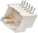 | SPECWR-WTB 2.00 mm Male Header, –, – | Simulation– | Verfügbarkeit – | Status Aktivi| Produktion ist aktiv. Erwartete Lebenszeit: >10 Jahre. | ProduktserieWR-WTB 2.00 mm Male Header | – | – | – | – | – | – | – | GenderMännlich | Pins30 | TypHorizontal | – | KontaktbeschichtungZinn | Nennstrom3 A | Arbeitsspannung250 V (AC) | Kontaktwiderstand20 mΩ | VerpackungTube | – | – | – | – | – | – | – | Betriebstemperatur -25 °C up to +85 °C | – | – | Isolationswiderstand1000 MΩ | – | Länge33.4 mm | – | – | – | – | – | – | – | – | MontageartTHT | Leiterplattendicke1.6 mm | FarbeWeiß | Polarität30 | Nennstrom [1]3 A | PCB/Kabel/PanelPCB | –Verfügbarkeit prüfen | |||||||||||||||||||||||||||||||||||||||||||||||||||||||||||||||||||||||||||||||||||||||||||||||||||||||||||||||||||||||||||||||||||||||||||||||||||||||||||||||||||||||||||||||||||||||||||||||||||||||||||||||||||||||||||||||||||||||||||||||||||||||||||||||||||||||||||||||||||||||||||||||||||||||||||||||||||||||||||||||||||||||||||||||||||||||||||||||||||||||||||||||||||||||||||||||||||||||||||||||||||||||||||||||||||||||||||||||||||||||||||||||||||||||||||||||||||||||||||||||||||||||||||||||||||||||||||||||||||||||||||||||||||||||||||||||||||||||||||||||||||||||||||||||||||||||||||||||||||||||||||||||||||||||||||||||||||||||||||||||||||||||||||||||||||||||||||||||||||||||||||||||||||||||||||||||||||||||||||||||||||||||||||||||||||||||||||||||||||||||||||||||||||||||||||||||||||||||||||||||||||||||||||||||||||||||||||||||||||||||||||||||||||||||||||||||||||||||||||||||||||||||||||||||||||||||||||||||||||||||||||||||||||||||||||||||||||||
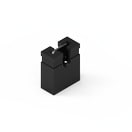
 | SPECWA-SPAII Plastic Spacer Stud, metric, internal/ internal, –, – | Simulation– | Verfügbarkeit – | Status Aktivi| Produktion ist aktiv. Erwartete Lebenszeit: >10 Jahre. | – | – | – | – | – | – | – | – | – | – | – | – | – | – | – | VerpackungBeutel | – | – | – | – | – | – | – | Betriebstemperatur -30 °C up to +110 °C | – | – | – | – | Länge8 mm | – | – | – | Schlüsselweite6 mm | InnengewindeM3 | BrennbarkeitsklasseUL94 HB | – | – | – | – | FarbeSchwarz | – | – | – | –Verfügbarkeit prüfen | ||||||||||||||||||||||||||||||||||||||||||||||||||||||||||||||||||||||||||||||||||||||||||||||||||||||||||||||||||||||||||||||||||||||||||||||||||||||||||||||||||||||||||||||||||||||||||||||||||||||||||||||||||||||||||||||||||||||||||||||||||||||||||||||||||||||||||||||||||||||||||||||||||||||||||||||||||||||||||||||||||||||||||||||||||||||||||||||||||||||||||||||||||||||||||||||||||||||||||||||||||||||||||||||||||||||||||||||||||||||||||||||||||||||||||||||||||||||||||||||||||||||||||||||||||||||||||||||||||||||||||||||||||||||||||||||||||||||||||||||||||||||||||||||||||||||||||||||||||||||||||||||||||||||||||||||||||||||||||||||||||||||||||||||||||||||||||||||||||||||||||||||||||||||||||||||||||||||||||||||||||||||||||||||||||||||||||||||||||||||||||||||||||||||||||||||||||||||||||||||||||||||||||||||||||||||||||||||||||||||||||||||||||||||||||||||||||||||||||||||||||||||||||||||||||||||||||||||||||||||||||||||||||||||||||||||||||||||
 | SPECWR-WTB 2.00 mm Female Dual Row Crimp Contact, –, – | Simulation– | Verfügbarkeit – | Status Aktivi| Produktion ist aktiv. Erwartete Lebenszeit: >10 Jahre. | ProduktserieWR-WTB 2.00 mm Female Dual Row Crimp Contact | – | – | – | – | – | – | – | GenderWeiblich | – | TypCrimpkontakt | Wire Section 28 to 22 (AWG) 0.081 to 0.326 (mm²) | KontaktbeschichtungZinn | Nennstrom3 A | Arbeitsspannung250 V (AC) | Kontaktwiderstand20 mΩ | Verpackunggroße Rolle | Verpackungseinheit10000 pcs | Stranded Wire Section (AWG)28 to 22 (AWG) | Stranded Wire Section (Metric)0.081 to 0.326 (mm²) | – | – | – | – | Betriebstemperatur -25 °C up to +85 °C | – | – | Isolationswiderstand1000 MΩ | – | – | – | – | – | – | – | – | – | – | – | – | – | – | Nennstrom [1]3 A | PCB/Kabel/PanelKabel | –Verfügbarkeit prüfen | |||||||||||||||||||||||||||||||||||||||||||||||||||||||||||||||||||||||||||||||||||||||||||||||||||||||||||||||||||||||||||||||||||||||||||||||||||||||||||||||||||||||||||||||||||||||||||||||||||||||||||||||||||||||||||||||||||||||||||||||||||||||||||||||||||||||||||||||||||||||||||||||||||||||||||||||||||||||||||||||||||||||||||||||||||||||||||||||||||||||||||||||||||||||||||||||||||||||||||||||||||||||||||||||||||||||||||||||||||||||||||||||||||||||||||||||||||||||||||||||||||||||||||||||||||||||||||||||||||||||||||||||||||||||||||||||||||||||||||||||||||||||||||||||||||||||||||||||||||||||||||||||||||||||||||||||||||||||||||||||||||||||||||||||||||||||||||||||||||||||||||||||||||||||||||||||||||||||||||||||||||||||||||||||||||||||||||||||||||||||||||||||||||||||||||||||||||||||||||||||||||||||||||||||||||||||||||||||||||||||||||||||||||||||||||||||||||||||||||||||||||||||||||||||||||||||||||||||||||||||||||||||||||||||||||||||||||||
 | SPECWR-PHD Kurzschlussbrücken, –, – | Simulation– | Verfügbarkeit – | Status Aktivi| Produktion ist aktiv. Erwartete Lebenszeit: >10 Jahre. | ProduktserieWR-PHD Kurzschlussbrücken | – | – | – | – | – | – | – | GenderJumper | Pins1 | – | – | KontaktbeschichtungGold | Nennstrom3 A | Arbeitsspannung250 V (AC) | Kontaktwiderstand20 mΩ | VerpackungBeutel | – | – | – | – | – | – | – | Betriebstemperatur -40 °C up to +125 °C | – | – | Isolationswiderstand1000 MΩ | – | Länge2.44 mm | – | – | – | – | – | – | – | – | – | – | FarbeSchwarz | – | – | – | –Verfügbarkeit prüfen | |||||||||||||||||||||||||||||||||||||||||||||||||||||||||||||||||||||||||||||||||||||||||||||||||||||||||||||||||||||||||||||||||||||||||||||||||||||||||||||||||||||||||||||||||||||||||||||||||||||||||||||||||||||||||||||||||||||||||||||||||||||||||||||||||||||||||||||||||||||||||||||||||||||||||||||||||||||||||||||||||||||||||||||||||||||||||||||||||||||||||||||||||||||||||||||||||||||||||||||||||||||||||||||||||||||||||||||||||||||||||||||||||||||||||||||||||||||||||||||||||||||||||||||||||||||||||||||||||||||||||||||||||||||||||||||||||||||||||||||||||||||||||||||||||||||||||||||||||||||||||||||||||||||||||||||||||||||||||||||||||||||||||||||||||||||||||||||||||||||||||||||||||||||||||||||||||||||||||||||||||||||||||||||||||||||||||||||||||||||||||||||||||||||||||||||||||||||||||||||||||||||||||||||||||||||||||||||||||||||||||||||||||||||||||||||||||||||||||||||||||||||||||||||||||||||||||||||||||||||||||||||||||||||||||||||||||||||
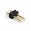 | SPECWR-PHD Stiftleisten - Einreihig, –, – | Simulation– | Verfügbarkeit – | Status Aktivi| Produktion ist aktiv. Erwartete Lebenszeit: >10 Jahre. | ProduktserieWR-PHD Stiftleisten - Einreihig | – | – | – | – | – | – | – | GenderStiftleiste | Pins2 | TypGerade | – | KontaktbeschichtungGold | Nennstrom3 A | Arbeitsspannung250 V (AC) | Kontaktwiderstand20 mΩ | VerpackungBeutel | – | – | – | – | – | – | – | Betriebstemperatur -40 °C up to +105 °C | – | – | Isolationswiderstand1000 MΩ | – | Länge5.08 mm | – | – | – | – | – | – | – | – | MontageartTHT | – | – | – | – | – | –Verfügbarkeit prüfen | |||||||||||||||||||||||||||||||||||||||||||||||||||||||||||||||||||||||||||||||||||||||||||||||||||||||||||||||||||||||||||||||||||||||||||||||||||||||||||||||||||||||||||||||||||||||||||||||||||||||||||||||||||||||||||||||||||||||||||||||||||||||||||||||||||||||||||||||||||||||||||||||||||||||||||||||||||||||||||||||||||||||||||||||||||||||||||||||||||||||||||||||||||||||||||||||||||||||||||||||||||||||||||||||||||||||||||||||||||||||||||||||||||||||||||||||||||||||||||||||||||||||||||||||||||||||||||||||||||||||||||||||||||||||||||||||||||||||||||||||||||||||||||||||||||||||||||||||||||||||||||||||||||||||||||||||||||||||||||||||||||||||||||||||||||||||||||||||||||||||||||||||||||||||||||||||||||||||||||||||||||||||||||||||||||||||||||||||||||||||||||||||||||||||||||||||||||||||||||||||||||||||||||||||||||||||||||||||||||||||||||||||||||||||||||||||||||||||||||||||||||||||||||||||||||||||||||||||||||||||||||||||||||||||||||||||||||||
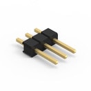 | SPECWR-PHD Stiftleisten - Einreihig, –, – | Simulation– | Verfügbarkeit – | Status Aktivi| Produktion ist aktiv. Erwartete Lebenszeit: >10 Jahre. | ProduktserieWR-PHD Stiftleisten - Einreihig | – | – | – | – | – | – | – | GenderStiftleiste | Pins3 | TypGerade | – | KontaktbeschichtungGold | Nennstrom3 A | Arbeitsspannung250 V (AC) | Kontaktwiderstand20 mΩ | VerpackungBeutel | – | – | – | – | – | – | – | Betriebstemperatur -40 °C up to +105 °C | – | – | Isolationswiderstand1000 MΩ | – | Länge7.62 mm | – | – | – | – | – | – | – | – | MontageartTHT | – | – | – | – | – | –Verfügbarkeit prüfen | |||||||||||||||||||||||||||||||||||||||||||||||||||||||||||||||||||||||||||||||||||||||||||||||||||||||||||||||||||||||||||||||||||||||||||||||||||||||||||||||||||||||||||||||||||||||||||||||||||||||||||||||||||||||||||||||||||||||||||||||||||||||||||||||||||||||||||||||||||||||||||||||||||||||||||||||||||||||||||||||||||||||||||||||||||||||||||||||||||||||||||||||||||||||||||||||||||||||||||||||||||||||||||||||||||||||||||||||||||||||||||||||||||||||||||||||||||||||||||||||||||||||||||||||||||||||||||||||||||||||||||||||||||||||||||||||||||||||||||||||||||||||||||||||||||||||||||||||||||||||||||||||||||||||||||||||||||||||||||||||||||||||||||||||||||||||||||||||||||||||||||||||||||||||||||||||||||||||||||||||||||||||||||||||||||||||||||||||||||||||||||||||||||||||||||||||||||||||||||||||||||||||||||||||||||||||||||||||||||||||||||||||||||||||||||||||||||||||||||||||||||||||||||||||||||||||||||||||||||||||||||||||||||||||||||||||||||||
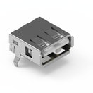 | SPECWR-USB Standard Connectors, –, – | Simulation– | Verfügbarkeit – | Status Aktivi| Produktion ist aktiv. Erwartete Lebenszeit: >10 Jahre. | ProduktserieWR-USB Standard Connectors | – | – | – | – | – | – | – | GenderBuchse | Pins4 | TypHorizontal | – | Kontaktbeschichtungselektiv vergoldet | Nennstrom1.5 A | Arbeitsspannung30 V (AC) | Kontaktwiderstand20 mΩ | VerpackungTray | – | – | – | – | – | – | – | Betriebstemperatur -40 °C up to +105 °C | – | – | Isolationswiderstand1000 MΩ | – | – | – | – | – | – | – | – | AnwendungUSB 2.0 | Interface typType A | MontageartTHT | – | FarbeWeiß | – | Nennstrom [1]1.5 A | – | –Verfügbarkeit prüfen | |||||||||||||||||||||||||||||||||||||||||||||||||||||||||||||||||||||||||||||||||||||||||||||||||||||||||||||||||||||||||||||||||||||||||||||||||||||||||||||||||||||||||||||||||||||||||||||||||||||||||||||||||||||||||||||||||||||||||||||||||||||||||||||||||||||||||||||||||||||||||||||||||||||||||||||||||||||||||||||||||||||||||||||||||||||||||||||||||||||||||||||||||||||||||||||||||||||||||||||||||||||||||||||||||||||||||||||||||||||||||||||||||||||||||||||||||||||||||||||||||||||||||||||||||||||||||||||||||||||||||||||||||||||||||||||||||||||||||||||||||||||||||||||||||||||||||||||||||||||||||||||||||||||||||||||||||||||||||||||||||||||||||||||||||||||||||||||||||||||||||||||||||||||||||||||||||||||||||||||||||||||||||||||||||||||||||||||||||||||||||||||||||||||||||||||||||||||||||||||||||||||||||||||||||||||||||||||||||||||||||||||||||||||||||||||||||||||||||||||||||||||||||||||||||||||||||||||||||||||||||||||||||||||||||||||||||||||
SPECWCAP-CSGP MLCCs 100 V(DC), –, – | Verfügbarkeit – | Downloads7 Dateien | Status Aktivi| Produktion ist aktiv. Erwartete Lebenszeit: >10 Jahre. | ProduktserieWCAP-CSGP MLCCs 100 V(DC) | – | – | – | – | – | – | – | – | – | – | – | – | – | – | – | Verpackung7" Tape & Reel | Verpackungseinheit4000 pcs | – | – | Kapazität100 pF | Kapazität±10% | Nennspannung100 V (DC) | Bauform0603 | Betriebstemperatur -55 °C up to +125 °C | – | Verlustfaktor2.5 % | Isolationswiderstand10 GΩ | KeramiktypX7R Klasse II | Länge1.6 mm | Breite0.8 mm | Höhe0.8 mm | Pad Dimension0.4 mm | – | – | – | – | – | – | – | – | – | – | – | –Verfügbarkeit prüfen | ||||||||||||||||||||||||||||||||||||||||||||||||||||||||||||||||||||||||||||||||||||||||||||||||||||||||||||||||||||||||||||||||||||||||||||||||||||||||||||||||||||||||||||||||||||||||||||||||||||||||||||||||||||||||||||||||||||||||||||||||||||||||||||||||||||||||||||||||||||||||||||||||||||||||||||||||||||||||||||||||||||||||||||||||||||||||||||||||||||||||||||||||||||||||||||||||||||||||||||||||||||||||||||||||||||||||||||||||||||||||||||||||||||||||||||||||||||||||||||||||||||||||||||||||||||||||||||||||||||||||||||||||||||||||||||||||||||||||||||||||||||||||||||||||||||||||||||||||||||||||||||||||||||||||||||||||||||||||||||||||||||||||||||||||||||||||||||||||||||||||||||||||||||||||||||||||||||||||||||||||||||||||||||||||||||||||||||||||||||||||||||||||||||||||||||||||||||||||||||||||||||||||||||||||||||||||||||||||||||||||||||||||||||||||||||||||||||||||||||||||||||||||||||||||||||||||||||||||||||||||||||||||||||||||||||||||||||||
SPECWCAP-CSGP MLCCs 100 V(DC), –, – | Verfügbarkeit – | Downloads7 Dateien | Status Aktivi| Produktion ist aktiv. Erwartete Lebenszeit: >10 Jahre. | ProduktserieWCAP-CSGP MLCCs 100 V(DC) | – | – | – | – | – | – | – | – | – | – | – | – | – | – | – | Verpackung7" Tape & Reel | – | – | – | Kapazität100 nF | Kapazität±10% | Nennspannung100 V (DC) | Bauform0603 | Betriebstemperatur -55 °C up to +125 °C | – | Verlustfaktor5 % | Isolationswiderstand1 GΩ | KeramiktypX7R Klasse II | Länge1.6 mm | Breite0.8 mm | Höhe0.8 mm | Pad Dimension0.4 mm | – | – | – | – | – | – | – | – | – | – | – | –Verfügbarkeit prüfen | ||||||||||||||||||||||||||||||||||||||||||||||||||||||||||||||||||||||||||||||||||||||||||||||||||||||||||||||||||||||||||||||||||||||||||||||||||||||||||||||||||||||||||||||||||||||||||||||||||||||||||||||||||||||||||||||||||||||||||||||||||||||||||||||||||||||||||||||||||||||||||||||||||||||||||||||||||||||||||||||||||||||||||||||||||||||||||||||||||||||||||||||||||||||||||||||||||||||||||||||||||||||||||||||||||||||||||||||||||||||||||||||||||||||||||||||||||||||||||||||||||||||||||||||||||||||||||||||||||||||||||||||||||||||||||||||||||||||||||||||||||||||||||||||||||||||||||||||||||||||||||||||||||||||||||||||||||||||||||||||||||||||||||||||||||||||||||||||||||||||||||||||||||||||||||||||||||||||||||||||||||||||||||||||||||||||||||||||||||||||||||||||||||||||||||||||||||||||||||||||||||||||||||||||||||||||||||||||||||||||||||||||||||||||||||||||||||||||||||||||||||||||||||||||||||||||||||||||||||||||||||||||||||||||||||||||||||||||
SPECWCAP-CSGP MLCCs 50 V(DC), –, – | Verfügbarkeit – | Status Aktivi| Produktion ist aktiv. Erwartete Lebenszeit: >10 Jahre. | ProduktserieWCAP-CSGP MLCCs 50 V(DC) | – | – | – | – | – | – | – | – | – | – | – | – | – | – | – | Verpackung7" Tape & Reel | – | – | – | Kapazität10 µF | Kapazität±10% | Nennspannung50 V (DC) | Bauform1210 | Betriebstemperatur -55 °C up to +125 °C | – | Verlustfaktor10 % | Isolationswiderstand0.01 GΩ | KeramiktypX7R Klasse II | Länge3.2 mm | Breite2.5 mm | Höhe2.5 mm | Pad Dimension0.6 mm | – | – | – | – | – | – | – | – | – | – | – | –Verfügbarkeit prüfen | |||||||||||||||||||||||||||||||||||||||||||||||||||||||||||||||||||||||||||||||||||||||||||||||||||||||||||||||||||||||||||||||||||||||||||||||||||||||||||||||||||||||||||||||||||||||||||||||||||||||||||||||||||||||||||||||||||||||||||||||||||||||||||||||||||||||||||||||||||||||||||||||||||||||||||||||||||||||||||||||||||||||||||||||||||||||||||||||||||||||||||||||||||||||||||||||||||||||||||||||||||||||||||||||||||||||||||||||||||||||||||||||||||||||||||||||||||||||||||||||||||||||||||||||||||||||||||||||||||||||||||||||||||||||||||||||||||||||||||||||||||||||||||||||||||||||||||||||||||||||||||||||||||||||||||||||||||||||||||||||||||||||||||||||||||||||||||||||||||||||||||||||||||||||||||||||||||||||||||||||||||||||||||||||||||||||||||||||||||||||||||||||||||||||||||||||||||||||||||||||||||||||||||||||||||||||||||||||||||||||||||||||||||||||||||||||||||||||||||||||||||||||||||||||||||||||||||||||||||||||||||||||||||||||||||||||||||||||
SPECWCAP-CSGP MLCCs 100 V(DC), –, – | Verfügbarkeit – | Downloads7 Dateien | Status Aktivi| Produktion ist aktiv. Erwartete Lebenszeit: >10 Jahre. | ProduktserieWCAP-CSGP MLCCs 100 V(DC) | – | – | – | – | – | – | – | – | – | – | – | – | – | – | – | Verpackung7" Tape & Reel | – | – | – | Kapazität2.2 µF | Kapazität±10% | Nennspannung100 V (DC) | Bauform1210 | Betriebstemperatur -55 °C up to +125 °C | – | Verlustfaktor5 % | Isolationswiderstand0.05 GΩ | KeramiktypX7R Klasse II | Länge3.2 mm | Breite2.5 mm | Höhe2.5 mm | Pad Dimension0.75 mm | – | – | – | – | – | – | – | – | – | – | – | –Verfügbarkeit prüfen | ||||||||||||||||||||||||||||||||||||||||||||||||||||||||||||||||||||||||||||||||||||||||||||||||||||||||||||||||||||||||||||||||||||||||||||||||||||||||||||||||||||||||||||||||||||||||||||||||||||||||||||||||||||||||||||||||||||||||||||||||||||||||||||||||||||||||||||||||||||||||||||||||||||||||||||||||||||||||||||||||||||||||||||||||||||||||||||||||||||||||||||||||||||||||||||||||||||||||||||||||||||||||||||||||||||||||||||||||||||||||||||||||||||||||||||||||||||||||||||||||||||||||||||||||||||||||||||||||||||||||||||||||||||||||||||||||||||||||||||||||||||||||||||||||||||||||||||||||||||||||||||||||||||||||||||||||||||||||||||||||||||||||||||||||||||||||||||||||||||||||||||||||||||||||||||||||||||||||||||||||||||||||||||||||||||||||||||||||||||||||||||||||||||||||||||||||||||||||||||||||||||||||||||||||||||||||||||||||||||||||||||||||||||||||||||||||||||||||||||||||||||||||||||||||||||||||||||||||||||||||||||||||||||||||||||||||||||||
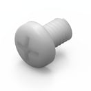 | SPECWA-SCRW Linsenkopfschraube M3 mit Kreuzschlitz, –, – | Simulation– | Verfügbarkeit – | Status Aktivi| Produktion ist aktiv. Erwartete Lebenszeit: >10 Jahre. | ProduktserieWA-SCRW Linsenkopfschraube M3 mit Kreuzschlitz | – | – | – | – | – | – | – | – | – | – | – | – | – | – | – | VerpackungLose | Verpackungseinheit2000 pcs | – | – | – | – | – | – | Betriebstemperatur -30 °C up to +85 °C | – | – | – | – | Länge4 mm | – | – | – | – | – | BrennbarkeitsklasseUL94 V-2 | – | – | – | – | FarbeNatur | – | – | – | –Verfügbarkeit prüfen | |||||||||||||||||||||||||||||||||||||||||||||||||||||||||||||||||||||||||||||||||||||||||||||||||||||||||||||||||||||||||||||||||||||||||||||||||||||||||||||||||||||||||||||||||||||||||||||||||||||||||||||||||||||||||||||||||||||||||||||||||||||||||||||||||||||||||||||||||||||||||||||||||||||||||||||||||||||||||||||||||||||||||||||||||||||||||||||||||||||||||||||||||||||||||||||||||||||||||||||||||||||||||||||||||||||||||||||||||||||||||||||||||||||||||||||||||||||||||||||||||||||||||||||||||||||||||||||||||||||||||||||||||||||||||||||||||||||||||||||||||||||||||||||||||||||||||||||||||||||||||||||||||||||||||||||||||||||||||||||||||||||||||||||||||||||||||||||||||||||||||||||||||||||||||||||||||||||||||||||||||||||||||||||||||||||||||||||||||||||||||||||||||||||||||||||||||||||||||||||||||||||||||||||||||||||||||||||||||||||||||||||||||||||||||||||||||||||||||||||||||||||||||||||||||||||||||||||||||||||||||||||||||||||||||||||||||||||
SPECWCAP-CSGP MLCCs 50 V(DC), –, – | Verfügbarkeit – | Status Aktivi| Produktion ist aktiv. Erwartete Lebenszeit: >10 Jahre. | ProduktserieWCAP-CSGP MLCCs 50 V(DC) | – | – | – | – | – | – | – | – | – | – | – | – | – | – | – | Verpackung7" Tape & Reel | – | – | – | Kapazität220 nF | Kapazität±5% | Nennspannung50 V (DC) | Bauform0603 | Betriebstemperatur -55 °C up to +125 °C | – | Verlustfaktor10 % | Isolationswiderstand2.3 GΩ | KeramiktypX7R Klasse II | Länge1.6 mm | Breite0.8 mm | Höhe0.8 mm | Pad Dimension0.4 mm | – | – | – | – | – | – | – | – | – | – | – | –Verfügbarkeit prüfen | |||||||||||||||||||||||||||||||||||||||||||||||||||||||||||||||||||||||||||||||||||||||||||||||||||||||||||||||||||||||||||||||||||||||||||||||||||||||||||||||||||||||||||||||||||||||||||||||||||||||||||||||||||||||||||||||||||||||||||||||||||||||||||||||||||||||||||||||||||||||||||||||||||||||||||||||||||||||||||||||||||||||||||||||||||||||||||||||||||||||||||||||||||||||||||||||||||||||||||||||||||||||||||||||||||||||||||||||||||||||||||||||||||||||||||||||||||||||||||||||||||||||||||||||||||||||||||||||||||||||||||||||||||||||||||||||||||||||||||||||||||||||||||||||||||||||||||||||||||||||||||||||||||||||||||||||||||||||||||||||||||||||||||||||||||||||||||||||||||||||||||||||||||||||||||||||||||||||||||||||||||||||||||||||||||||||||||||||||||||||||||||||||||||||||||||||||||||||||||||||||||||||||||||||||||||||||||||||||||||||||||||||||||||||||||||||||||||||||||||||||||||||||||||||||||||||||||||||||||||||||||||||||||||||||||||||||||||||
| Erwartete Verfügbarkeit | Eingehender Bestand | Menge |
|---|---|---|
| Aktuelle Verfügbarkeit | – | – |