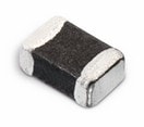
Infineon Technologies CYPAS111A0-24LQXQ | Demoboard CY-SD1122 18W USB-C PD
USB PD power adapter secondary side controller
Details
| Topologie | Sperrwandler |
| Eingangsspannung | 90-265 V |
| Schaltfrequenz | 20-150 kHz |
| IC-Revision | 4.2 |
Beschreibung
Cypress CYPAP111 part of PAG1P family is designed for a secondary controlled AC/DC flyback converter topology. In this topology, the voltage and current regulation is performed by the secondary controller. CYPAP111 is responsible for providing the start-up function, driving the primary side FET as well as responding to fault conditionsCypress CYPAS111 part of PAG1S family is an integrated secondary-side synchronous flyback controller, synchronous rectifier (SR) controller, and charging port controller. CYPAS111 is designed to fit a secondary-controlled flyback system with a primary startup controller (CYPAP111) with secondary-side sensing and regulation. CYPAS111 is targeted towards power adapters, it fits well into high-efficiency AC-DC flyback designs for USB Power Delivery, Qualcomm Quick Charge,and other standard charging protocols. CYPAS111 also supports USB Power Delivery (USB PD 3.0) Programmable Power Supply (PPS) mode.The interface between CYPAP111 and CYPAS111 is through a Pulse Edged Transformer and its associated circuitry.This document contains test results of PAG1P + PAG1S based 18W Power Adapter solution board (CY-SD1122). The tests were performed on this board which is equipped with Cypress CYPAP111A3-10SXQ on primary and CYPAS111A1-24LQXQ on secondary section of the converter.
Eigenschaften
- Integrates secondary-side regulation, synchronous rectifier (SR), and charging port controller
- Optimized efficiency across line and load range, meeting CoC Tier 2 and DoE level 6 requirements
- Supports quasi-resonant (QR) or critical conduction mode (CrCM), valley switching, discontinuous conduction mode (DCM), and burst mode for light load operations
- No load power consumption of < 30 mW with EZ-PD™ PAG1P designs
- Switching frequency range of 20 kHz to 150 kHz
- Supports feed-forward line sensing for faster transient line response
- Supports constant voltage (CV) and constant current (CC) modes of operation.
- Configurable overvoltage protection (OVP), undervoltage protection (UVP), overcurrent protection (OCP), short circuit protection (SCP), and over-temperature protection (OTP)
- USB PD 3.0 compliant with PPS (USB-IF certified, TID:1475)
- Supports USB PD 2.0, PD 3.0 with PPS, QC4+, QC 4.0, QC3.0, QC 2.0, Samsung AFC, Apple charging, and BC v1.2 charging protocols
- Integrates low-side current sense amplifier (LSCSA), 2x VBUS discharge FETs, and a NFET gate driver to drive the load switch
- Protects against accidental VBUS to CC short; ESD protection on CC, VBUS, and DP/DM lines
- 24-QFN package with –40°C to +105°C extended industrial temperature range
Typische Anwendungen
- USB PD 3.0 PPS power adapter, Quick Charge 4.0 power adapter, Power adapters supporting both USB PD and legacy charging
Weiterführende Informationen
Artikeldaten
| Artikel Nr. | Datenblatt | Simulation | Downloads | Status | Produktserie | C | Tol. C | VR (V (DC)) | Bauform | Betriebstemperatur | Q (%) | DF (%) | RISO | Keramiktyp | L (mm) | W (mm) | H (mm) | Fl (mm) | Verpackung | Z @ 100 MHz (Ω) | Zmax (Ω) | Testbedingung Zmax | IR 2 (mA) | RDC max. (Ω) | Typ | Muster | |
|---|---|---|---|---|---|---|---|---|---|---|---|---|---|---|---|---|---|---|---|---|---|---|---|---|---|---|---|
| 885012005025 | SPEC | 9 Dateien | Aktiv i| Produktion ist aktiv. Erwartete Lebenszeit: >10 Jahre. | WCAP-CSGP MLCCs 16 V(DC) | 10 pF | ±5% | 16 | 0402 | -55 °C up to +125 °C | 600 | – | 10 GΩ | NP0 Klasse I | 1 | 0.5 | 0.5 | 0.25 | 7" Tape & Reel | – | – | – | – | – | – | |||
| 885012006017 | SPEC | 9 Dateien | Aktiv i| Produktion ist aktiv. Erwartete Lebenszeit: >10 Jahre. | WCAP-CSGP MLCCs 16 V(DC) | 10 pF | ±5% | 16 | 0603 | -55 °C up to +125 °C | 600 | – | 10 GΩ | NP0 Klasse I | 1.6 | 0.8 | 0.8 | 0.4 | 7" Tape & Reel | – | – | – | – | – | – | |||
| 885012205020 | SPEC | 9 Dateien | Aktiv i| Produktion ist aktiv. Erwartete Lebenszeit: >10 Jahre. | WCAP-CSGP MLCCs 16 V(DC) | 150 pF | ±10% | 16 | 0402 | -55 °C up to +125 °C | – | 3.5 | 10 GΩ | X7R Klasse II | 1 | 0.5 | 0.5 | 0.25 | 7" Tape & Reel | – | – | – | – | – | – | |||
 | 742792040 | SPEC | 9 Dateien | Aktiv i| Produktion ist aktiv. Erwartete Lebenszeit: >10 Jahre. | WE-CBF SMT-Ferrit | – | – | – | 0805 | -55 °C up to +125 °C | – | – | – | – | 2 | 1.2 | 0.0009 | 0.5 | – | 600 | 700 | 150 MHz | 2000 | 0.15 | Hochstrom |
| Artikel Nr. | Datenblatt | Simulation | |
|---|---|---|---|
| 885012005025 | SPEC | ||
| 885012006017 | SPEC | ||
| 885012205020 | SPEC | ||
 | 742792040 | SPEC |
| Muster |
|---|
| Artikel Nr. | Datenblatt | Simulation | Downloads | Status | Produktserie | C | Tol. C | VR (V (DC)) | Bauform | Betriebstemperatur | Q (%) | DF (%) | RISO | Keramiktyp | L (mm) | W (mm) | H (mm) | Fl (mm) | Verpackung | Z @ 100 MHz (Ω) | Zmax (Ω) | Testbedingung Zmax | IR 2 (mA) | RDC max. (Ω) | Typ | Muster |
|---|


