Does it just not fit?Get in contact with us to check our warehouses around the globe to prioritize your order.Contact us
Würth Elektronik capacitors
Big portfolio available ex stock
Würth Elektronik capacitors
Big portfolio available ex stock
Würth Elektronik has extended its capacitor portfolio. You will find an overview of our current technologies available ex stock in the graph. More details (e.g. series, characteristics, features, applications, etc.) about each product family can be found in the flyer or for example below. In our flyer you will also find information about our services.
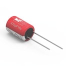
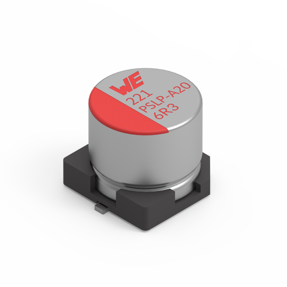
Aluminum polymer capacitors are wound capacitors. These consist of aluminum foils with a layer of paper in between.
Layer structure
The aluminum foil of the anode is formed by anodic oxidation before the winding process, so that the dielectric (oxide layer) is strengthened. The winding is impregnated with a monomer. The highly conductive polymer is formed by polymerisation. The paper interlayer ensures an even structure and a defined distance between the anode and cathode foil.
Example applications
Router
Graphic card
Industrial computer
High power USB charger
Measurements
Redexpert
Measurements
Redexpert
With the help of REDEXPERT you will find the right capacitor based on your technical requirements. The tool supports, for example, with measured values for capacitance, impedance, ESR and dissipation factor (DF). The ability to compare individual components with each other in terms of measured values enables convenient component selection.
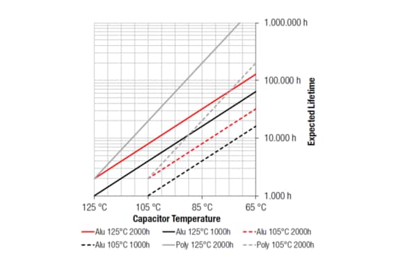
With this tool you can calculate your maximum expected lifetime. Depending on the product family, a different formula is used for the calculation. This calculator can be found in the aluminum capacitor module on the REDEXPERT platform.
In this graph you can find the difference in expected lifetime between our different product families. The curves are based on the different formulas and the endurance of this product. The lifetime table and formula can be found in the information sheet.
Introduction to the capacitor technologies and how to use them
Webinar
Introduction to the capacitor technologies and how to use them
Capacitors make up two thirds of all electronic components and there is a huge diversity of technologies which can overwhelm young engineers. All capacitors store electrical energy in the electrical field created in a dielectric material and they are used for very diverse applications like voltage stability and filtering. How that works differs between tiny MLCCs and huge electrolytic cells, from pF ratings up to the hundreds of Farads in supercapacitors. In this presentation, we introduce different capacitor solutions taking into account the advantages and disadvantages and with a focus on the final application.
Application notes and documents
Part Description System
Every capacitor is clearly defined by its technical part number. Depending on the technology, it captures all essential parameters at a glance, from package type and capacitance to rated voltage, temperature rating and packaging.
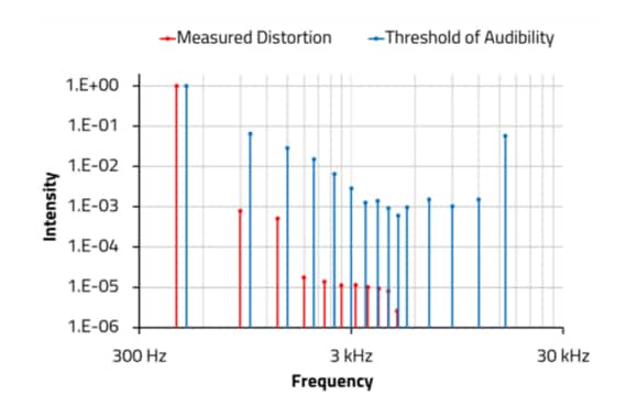
There is an ongoing discussion within the audio engineering community about the sound quality of amplifiers concerning the audibility of signal distortions. Apparently, capacitors used for coupling and decoupling signals are suspected to be the source or at least a contributor to high-frequency distortions that influence the hearing impression.
Application Note ANP071: Aluminum Electrolytic vs. Aluminum Polymer Capacitor and how its benefits are used properly
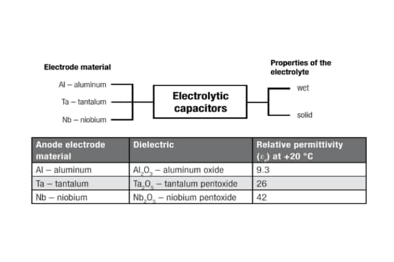
Aluminum polymer capacitor is a sub-form of the electrolytic capacitors. The special feature of these capacitor types is that a conductive polymer is used instead of a liquid electrolyte. This requires a special processing step, which is carried out during production. In this chemical reaction, the so-called polymerization, by heating, the still liquid monomer that has been impregnated in place of electrolyte in the separator paper is cross-linked to a solid polymer.
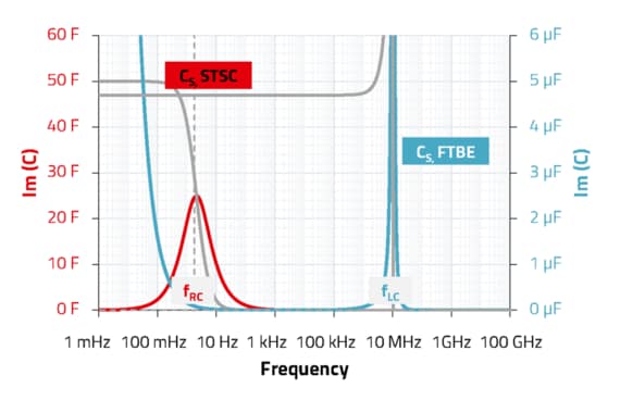
ANP109: Impedance Spectra of Different Capacitor Technologies
Impedance and capacitance spectra (or scattering parameters) are common representations of frequency dependent electrical properties of capacitors. The interpretation of such spectra provides a wide range of electrochemical, physical and technical relevant information. Those need to be separated from the ever-present measurement artifacts as well as parasitic effects.
Support Note SN008: Expected Lifetime of Aluminum Electrolytic and Aluminum Polymer Capacitor
The life cycle of a capacitor depends on many factors of the application. An important factor is the temperature or rather thermal load, as it is responsible for the fact that internal structures age over time and the electrical properties deteriorate. This results in increased leakage current, increasing the ESR, which in turn leads to a further increase of the temperature.
Support Note SN019: Afraid of aging? The effects of time on electrolytic capacitors
Since the development and production of electrolytic capacitors, designers have had to deal with the issues of aging and shelf life of these products. Electrolytic capacitors have been around for a very long time, but the rapid increase did not occur until the 1960s. There are still many "myths" from that time that revolve around the aging and shelf life of these capacitors.
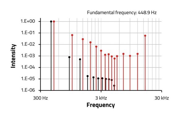
ANP125 Acoustic Effect of Harmonic Distortions caused by Aluminum Electrolytic Capacitors
This note reports a comparative study of total harmonic distortions (THD) caused by commercial electrolytic capacitors, as produced by Würth Elektronik eiSos as well as purpose-built items. The discussion about the audibility of distortions is made on the basis of human sound perception. This note arrives at the conclusion that capacitors do not add significant distortions to fundamental frequencies as they transfer signals. Modifications of the electrolyte or separation paper have almost no effect on the THD.
For most parts you can find the detailed information about packaging in the datasheet: If you cannot find them, please get in contact with Würth Elektronik. E.g. you can use the chat on the website.
Example: Page 3 of WCAP-CSRF component datasheet.
You can find the certifications in the datasheet, page 2.
In the case of X/Y safety capacitors, certification information can be found in PDF format in the online platform REDEXPERT.
These links are shown at the right end of the table, under the column “Certificates”.
We provide the document with all the values on our homepage.
You can also download the document by searching for “FIT” or “MTBF” in our download center.
This document reveals the FIT (Failures in time) and MTBF (Mean time between failures) values that can be calculated for each series based on the electrical stress (voltage applied in the case of capacitors) and the temperature applied according to calculation models of Telcordia SR-332 Issue 3.
Please refer to the table of contents at the beginning of the document to find the values for capacitors.
Würth Elektronik part number
Actual ambient operating temperature which the capacitor is used at (°C)
Operating ripple current flowing through the capacitor (A, RMS)
Frequency of the ripple current (Hz)
Operating voltage which is applied to the capacitor (V(DC))
Please find the following example (datasheet, page 2)
For all capacitors of series WCAP-A***, WCAP-P*** and WCAP-H*** there is a maximum ripple current in the datasheet. This ripple current is defined at a specific frequency and temperature and it is given as a RMS (root mean square) value.
Since the ripple current is defined at a certain frequency, it can be converted into the respective value for certain frequencies using factors. These factors can be found in the data sheet.
Let’s assume that the rated ripple current of this part (400V part) is 1 A @ 120 Hz. The max. ripple current @ max. temperature and 10 kHz is then 1.41 A.Furthermore, the ripple current can also be increased if the temperature is below the maximum component temperature. However, this must always be considered in the context of the expected lifetime.
The lifetime calculation in RedExpert can be used for a simple estimate. For detailed considerations, please use one of the many ways of contacting Würth Elektronik to obtain a specific lifetime estimate for your capacitor selection. This value may be increased or decreased if the operating conditions in the application are different from the datasheet.
You can find the lifetime calculation on REDEXPERT.
The lifetime calculator may be opened with the sand clock button in the left of the Electrolytic/Polymer/Hybrid . The user must be registered and logged, as this functionality is restricted to registered users.
You can set the conditions in the input box and for Frequency and Temperature you may also move the sliders in the graphs in the right.