IC manufacturers (106)
- All manufacturers
 Analog Devices
 Infineon Technologies
 Microchip
 Onsemi
 Renesas
 ROHM
ROHM STMicroelectronics
 Texas Instruments
- 3peak incorporated (35)
- Ablic (23)
- Acco Semiconductor (1)
- Advanced Power (4)
- Allegro Microsystems (100)
- Alpha & Omega Semiconductor (37)
- AnalogySemi (3)
- AnDAPT Inc (204)
- Anpec (13)
- AXElite (2)
- Backward (6)
- Bright Power Semiconductor (1)
- Broadcom (46)
- Cambridge GaN Devices (18)
- Chipanalog Micro (10)
- Cologne Chips (1)
- Convenient Power (1)
- Dialog Semiconductor (12)
- Diodes Incorporated (257)
- Divimath (8)
- Elmos AG (1)
- EPC (146)
- e-Peas Semiconductors (1)
- Eta Solutions Co. Ltd. (9)
- GaN Systems (8)
- GaNPower (3)
- Giantec (1)
- Gosemicon (2)
- Gstek Wuxi (1)
- Helix Semiconductor (7)
- IKON (1)
- Indie Semiconductor (8)
- Innovision Semiconductor Inc (2)
- Intel (68)
- Inventchip Technology (3)
- ISSI (51)
- JoulWatt (20)
- KDPOF (3)
- Kinetic Technology (8)
- Lattice semiconductor Corporation (38)
- Littelfuse (1)
- Lumissil Microsystems (8)
- M3 Technology (M3Tek) (7)
- Macnica (22)
- Marvell Semiconductor (1)
- MaxLinear (181)
- Menlo Micro (1)
- MikroE (25)
- MindCet (2)
- Monolithic Power Systems (983)
- Navitas Semiconductor Inc (6)
- NewEdge Technologies, Inc. (1)
- Nexperia (268)
- Nisshinbo Micro Device Inc. (9)
- Nordic Semiconductor (1)
- Novosense Micro (1)
- NXP (343)
- O2 Micro International Ltd (10)
- On Bright (7)
- Panasonic (2)
- PN Junction Semiconductor (2)
- Power Integrations (117)
- Powermat (1)
- Pulsiv (19)
- Qorvo (99)
- Realsil SuRealsil(tek) Microelectronics (1)
- Richtek (297)
- Sanken Electric Co., Ltd. (16)
- Sckipio (6)
- Semtech (86)
- SG-Micro (59)
- SiFive (2)
- Silanna Semiconductor (9)
- Silergy Corporation (34)
- Silicon Laboratory Inc. (108)
- Silicontent Technology (59)
- Silvertel (59)
- Skycore Semiconductors (1)
- Skyworks (33)
- Southchip (25)
- Summit Wireless (1)
- Tagore Tech (7)
- Taiwan Semiconductor (1)
- TDK Corporation (1)
- Tempo Semiconductor (1)
- Torex (37)
- Toshiba (27)
- Transphorm (21)
- TransSIP (2)
- Union (21)
- uPI Semiconductor (2)
- Valens Semiconductor (31)
- VisIC (1)
- Wise Integration (3)
- Wolfspeed (23)
- Xilinx (22)
- XL Semiconductor (3)
- XYSemi (62)
Overview
| Topology | Flyback Converter |
| Input voltage | 1.65-1.95 V |
| Output 1 | 3.6 V |
| IC revision | A |
Description
Incorporates the ARM926EJ-S™ ARM® Thumb® Processor– DSP instruction Extensions, ARM Jazelle® Technology for Java® Acceleration– 8 Kbyte Data Cache, 16 Kbyte Instruction Cache, Write Buffer– 200 MIPS at 180 MHz– Memory Management Unit– EmbeddedICE™, Debug Communication Channel Support• Additional Embedded Memories– One 32 Kbyte Internal ROM, Single-cycle Access at Maximum Matrix Speed– One 32 Kbyte (for AT91SAM9XE256 and AT91SAM9XE512) or 16 Kbyte (for AT91SAM9XE128) Internal SRAM, Single-cycleAccess at Maximum Matrix Speed– 128, 256 or 512 Kbytes of Internal High-speed Flash for AT91SAM9XE128, AT91SAM9XE256 or AT91SAM9XE512Respectively. Organized in 256, 512 or 1024 Pages of 512 Bytes Respectively.• 128-bit Wide Access• Fast Read Time: 60 ns• Page Programming Time: 4 ms, Including Page Auto-erase,Full Erase Time: 10 ms• 10,000 Write Cycles, 10 Years Data Retention, Page Lock Capabilities, Flash Security Bit• Enhanced Embedded Flash Controller (EEFC)– Interface of the Flash Block with the 32-bit Internal Bus– Increases Performance in ARM and Thumb Mode with 128-bit Wide Memory Interface• External Bus Interface (EBI)– Supports SDRAM, Static Memory, ECC-enabled NAND Flash and CompactFlash™• USB 2.0 Full Speed (12 Mbits per second) Device Port– On-chip Transceiver, 2,688-byte Configurable Integrated DPRAM• USB 2.0 Full Speed (12 Mbits per second) Host Single Port in the 208-pin PQFP Device and Double Port in 217-ball LFBGADevice– Single or Dual On-chip Transceivers– Integrated FIFOs and Dedicated DMA Channels• Ethernet MAC 10/100 Base-T– Media Independent Interface or Reduced Media Independent Interface– 28-byte FIFOs and Dedicated DMA Channels for Receive and Transmit• Image Sensor Interface– ITU-R BT. 601/656 External Interface, Programmable Frame Capture Rate– 12-bit Data Interface for Support of High Sensibility Sensors– SAV and EAV Synchronization, Preview Path with Scaler, YCbCr Format• Bus Matrix– Six 32-bit-layer Matrix– Remap Command3-2 AT91SAM9XE-EK Evaluation Board User Guide6311A–ATARM–04-Feb-08• Fully-featured System Controller, including– Reset Controller, Shutdown Controller– Four 32-bit Battery Backup Registers for a Total of 16 Bytes– Clock Generator and Power Management Controller– Advanced Interrupt Controller and Debug Unit– Periodic Interval Timer, Watchdog Timer and Real-time Timer• Reset Controller (RSTC)– Based on a Power-on Reset Cell, Reset Source Identification and Reset Output Control• Clock Generator (CKGR)– Selectable 32,768 Hz Low-power Oscillator or Internal Low Power RC Oscillator on Battery Backup Power Supply,Providing a Permanent Slow Clock– 3 to 20 MHz On-chip Oscillator, One Up to 240 MHz PLL and One Up to 100 MHz PLL• Power Management Controller (PMC)– Very Slow Clock Operating Mode, Software Programmable Power Optimization Capabilities– Two Programmable External Clock Signals• Advanced Interrupt Controller (AIC)– Individually Maskable, Eight-level Priority, Vectored Interrupt Sources– Three External Interrupt Sources and One Fast Interrupt Source, Spurious Interrupt Protected• Debug Unit (DBGU)– 2-wire UART and support for Debug Communication Channel, Programmable ICE Access Prevention• Periodic Interval Timer (PIT)– 20-bit Interval Timer Plus 12-bit Interval Counter• Watchdog Timer (WDT)– Key-protected, Programmable Only Once, Windowed 16-bit Counter Running at Slow Clock• Real-Time Timer (RTT)– 32-bit Free-running Backup Counter Running at Slow Clock with 16-bit Prescaler• One 4-channel 10-bit Analog to Digital Converter• Three 32-bit Parallel Input/Output Controllers (PIOA, PIOB, PIOC,)– 96 Programmable I/O Lines Multiplexed with up to Two Peripheral I/Os– Input Change Interrupt Capability on Each I/O Line– Individually Programmable Open-drain, Pull-up Resistor and Synchronous Output• Peripheral DMA Controller Channels (PDC)• Two-slot Multimedia Card Interface (MCI)– SDCard/SDIO and MultiMediaCard™ Compliant– Automatic Protocol Control and Fast Automatic Data Transfers with PDC• One Synchronous Serial Controllers (SSC)– Independent Clock and Frame Sync Signals for Each Receiver and Transmitter– I²S Analog Interface Support, Time Division Multiplex Support– High-speed Continuous Data Stream Capabilities with 32-bit Data Transfer• Four Universal Synchronous/Asynchronous Receiver Transmitters (USART)– Individual Baud Rate Generator, IrDA® Infrared Modulation/Demodulation– Support for ISO7816 T0/T1 Smart Card, Hardware Handshaking, RS485 Support– Full Modem Signal Control on USART0• One 2-wire UART• Two Master/Slave Serial Peripheral Interface (SPI)– 8- to 16-bit Programmable Data Length, Four External Peripheral Chip Selects– Synchronous Communications• Two Three-channel 16-bit Timer/Counters (TC)– Three External Clock Inputs, Two Multi-purpose I/O Pins per Channel– Double PWM Generation, Capture/Waveform Mode, Up/Down Capability– High-Drive Capability on Outputs TIOA0, TIOA1, TIOA2AT91SAM9XE-EK Evaluation Board User Guide 3-36311A–ATARM–04-Feb-08• Two Two-wire Interfaces (TWI)– Master, Multi-master and Slave Mode Operation– General Call Supported in Slave Mode– Connection to PDC Channel to Optimize Data Transfers in Master Mode Only• IEEE® 1149.1 JTAG Boundary Scan on All Digital Pins• Required Power Supplies:– 1.65V to 1.95V for VDDBU, VDDCORE and VDDPLL– 1.65V to 3.6V for VDDIOP1 (Peripheral I/Os)– 3.0V to 3.6V for VDDIOP0 and VDDANA (Analog-to-digital Converter)– Programmable 1.65V to 1.95V or 3.0V to 3.6V for VDDIOM (Memory I/Os)• Available in a 208-pin PQFP Green and a 217-ball LFBGA Green Package
Features
– Reset Controller, Shutdown Controller
– Four 32-bit Battery Backup Registers for a Total of 16 Bytes
– Clock Generator and Power Management Controller
– Advanced Interrupt Controller and Debug Unit
– Periodic Interval Timer, Watchdog Timer and Real-time Timer
Typical applications
- Audio
- Remote Communication
- Microcontroller
More information
Products
Order Code | Datasheet | Simulation | Downloads | Status | Product series | Z @ 100 MHz(Ω) | Zmax(Ω) | Test Condition Zmax | IR 2(mA) | RDC max.(Ω) | Type | SamplesAvailability & Sample | ||||||||||||||||||||||||||||||||||||||||||||||||||||||||||||||||||||||||||||||||||||||||||||||||||||||||||||||||||||||||||||||||||||||||||||||||||||||||||||||||||||||||||||||||||||||||||||||||||||||||||||||||||||||||||||||||||||||||||||||||||||||||||||||||||||||||||||||||||||||||||||||||||||||||||||||||||||||||||||||||||||||||||||||||||||||||||||||||||||||||||||||||||||||||||||||||||||||||||||||||||||||||||||||||||||||||||||||||||||||||||||||||||||||||||||||||||||||||||||||||||||||||||||||||||||||||||||||||||||||||||||||||||||||||||||||||||||||||||||||||||||||||||||||||||||||||||||||||||||||||||||||||||||||||||||||||||||||||||||||||||||||||||||||||||||||||||||||||||||||||||||||||||||||||||||||||||||||||||||||||||||||||||||||||||||||||||||||||||||||||||||||||||||||||||||||||||||||||||||||||||||||||||||||||||||||||||||||||||||||||||||||||||||||||||||||||||||||||||||||||||||||||||||||||||||||||||||||||||||||||||||||||||||||||||||||||||||||||||||||||||||||||||||||||||||||||||
|---|---|---|---|---|---|---|---|---|---|---|---|---|---|---|---|---|---|---|---|---|---|---|---|---|---|---|---|---|---|---|---|---|---|---|---|---|---|---|---|---|---|---|---|---|---|---|---|---|---|---|---|---|---|---|---|---|---|---|---|---|---|---|---|---|---|---|---|---|---|---|---|---|---|---|---|---|---|---|---|---|---|---|---|---|---|---|---|---|---|---|---|---|---|---|---|---|---|---|---|---|---|---|---|---|---|---|---|---|---|---|---|---|---|---|---|---|---|---|---|---|---|---|---|---|---|---|---|---|---|---|---|---|---|---|---|---|---|---|---|---|---|---|---|---|---|---|---|---|---|---|---|---|---|---|---|---|---|---|---|---|---|---|---|---|---|---|---|---|---|---|---|---|---|---|---|---|---|---|---|---|---|---|---|---|---|---|---|---|---|---|---|---|---|---|---|---|---|---|---|---|---|---|---|---|---|---|---|---|---|---|---|---|---|---|---|---|---|---|---|---|---|---|---|---|---|---|---|---|---|---|---|---|---|---|---|---|---|---|---|---|---|---|---|---|---|---|---|---|---|---|---|---|---|---|---|---|---|---|---|---|---|---|---|---|---|---|---|---|---|---|---|---|---|---|---|---|---|---|---|---|---|---|---|---|---|---|---|---|---|---|---|---|---|---|---|---|---|---|---|---|---|---|---|---|---|---|---|---|---|---|---|---|---|---|---|---|---|---|---|---|---|---|---|---|---|---|---|---|---|---|---|---|---|---|---|---|---|---|---|---|---|---|---|---|---|---|---|---|---|---|---|---|---|---|---|---|---|---|---|---|---|---|---|---|---|---|---|---|---|---|---|---|---|---|---|---|---|---|---|---|---|---|---|---|---|---|---|---|---|---|---|---|---|---|---|---|---|---|---|---|---|---|---|---|---|---|---|---|---|---|---|---|---|---|---|---|---|---|---|---|---|---|---|---|---|---|---|---|---|---|---|---|---|---|---|---|---|---|---|---|---|---|---|---|---|---|---|---|---|---|---|---|---|---|---|---|---|---|---|---|---|---|---|---|---|---|---|---|---|---|---|---|---|---|---|---|---|---|---|---|---|---|---|---|---|---|---|---|---|---|---|---|---|---|---|---|---|---|---|---|---|---|---|---|---|---|---|---|---|---|---|---|---|---|---|---|---|---|---|---|---|---|---|---|---|---|---|---|---|---|---|---|---|---|---|---|---|---|---|---|---|---|---|---|---|---|---|---|---|---|---|---|---|---|---|---|---|---|---|---|---|---|---|---|---|---|---|---|---|---|---|---|---|---|---|---|---|---|---|---|---|---|---|---|---|---|---|---|---|---|---|---|---|---|---|---|---|---|---|---|---|---|---|---|---|---|---|---|---|---|---|---|---|---|---|---|---|---|---|---|---|---|---|---|---|---|---|---|---|---|---|---|---|---|---|---|---|---|---|---|---|---|---|---|---|---|---|---|---|---|---|---|---|---|---|---|---|---|---|---|---|---|---|---|---|---|---|---|---|---|---|---|---|---|---|---|---|---|---|---|---|---|---|---|---|---|---|---|---|---|---|---|---|---|---|---|---|---|---|---|---|---|---|---|---|---|---|---|---|---|---|---|---|---|---|---|---|---|---|---|---|---|---|---|---|---|---|---|---|---|---|---|---|---|---|---|---|---|---|---|---|---|---|---|---|---|---|---|---|---|---|---|---|---|---|---|---|---|---|---|---|---|---|---|---|---|---|---|---|---|---|---|---|---|---|---|---|---|---|---|---|---|---|---|---|---|---|---|---|---|---|---|---|---|---|---|---|---|---|---|---|---|---|---|---|---|---|---|---|---|---|---|---|---|---|---|---|---|---|---|---|---|---|---|---|---|---|---|---|---|---|---|---|---|---|---|---|---|---|---|---|---|---|---|---|---|---|---|---|---|---|---|---|---|---|---|---|---|---|---|---|---|---|---|---|---|---|---|---|---|---|---|---|---|---|---|---|---|---|---|---|---|---|---|---|---|---|---|---|---|---|---|---|---|---|---|---|---|---|---|---|---|---|---|---|---|---|---|---|---|---|---|---|---|---|---|---|---|---|---|---|---|---|---|---|---|---|---|---|---|---|---|---|---|---|---|---|---|---|---|---|---|---|---|---|---|---|---|---|---|---|---|---|---|---|---|---|---|---|---|---|---|---|---|---|---|---|---|---|---|---|---|---|---|---|---|---|---|---|---|---|---|---|---|---|---|---|---|---|---|---|---|---|---|---|---|---|---|
| Log in now to view availability and request availability forecasts. LOGIN | ||||||||||||||||||||||||||||||||||||||||||||||||||||||||||||||||||||||||||||||||||||||||||||||||||||||||||||||||||||||||||||||||||||||||||||||||||||||||||||||||||||||||||||||||||||||||||||||||||||||||||||||||||||||||||||||||||||||||||||||||||||||||||||||||||||||||||||||||||||||||||||||||||||||||||||||||||||||||||||||||||||||||||||||||||||||||||||||||||||||||||||||||||||||||||||||||||||||||||||||||||||||||||||||||||||||||||||||||||||||||||||||||||||||||||||||||||||||||||||||||||||||||||||||||||||||||||||||||||||||||||||||||||||||||||||||||||||||||||||||||||||||||||||||||||||||||||||||||||||||||||||||||||||||||||||||||||||||||||||||||||||||||||||||||||||||||||||||||||||||||||||||||||||||||||||||||||||||||||||||||||||||||||||||||||||||||||||||||||||||||||||||||||||||||||||||||||||||||||||||||||||||||||||||||||||||||||||||||||||||||||||||||||||||||||||||||||||||||||||||||||||||||||||||||||||||||||||||||||||||||||||||||||||||||||||||||||||||||||||||||||||||||||||||||||||||||||||||||||||||
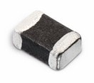 | SPECWE-CBF SMT EMI Suppression Ferrite Bead, 2200 Ω, 3000 Ω | Availability – | Status Activei| Production is active. Expected lifetime: >10 years. | Product seriesWE-CBF SMT EMI Suppression Ferrite Bead | Impedance @ 100 MHz2200 Ω | Maximum Impedance3000 Ω | Maximum Impedance80 MHz | Rated Current 2800 mA | DC Resistance0.6 Ω | TypeWide Band | –Check availability | |||||||||||||||||||||||||||||||||||||||||||||||||||||||||||||||||||||||||||||||||||||||||||||||||||||||||||||||||||||||||||||||||||||||||||||||||||||||||||||||||||||||||||||||||||||||||||||||||||||||||||||||||||||||||||||||||||||||||||||||||||||||||||||||||||||||||||||||||||||||||||||||||||||||||||||||||||||||||||||||||||||||||||||||||||||||||||||||||||||||||||||||||||||||||||||||||||||||||||||||||||||||||||||||||||||||||||||||||||||||||||||||||||||||||||||||||||||||||||||||||||||||||||||||||||||||||||||||||||||||||||||||||||||||||||||||||||||||||||||||||||||||||||||||||||||||||||||||||||||||||||||||||||||||||||||||||||||||||||||||||||||||||||||||||||||||||||||||||||||||||||||||||||||||||||||||||||||||||||||||||||||||||||||||||||||||||||||||||||||||||||||||||||||||||||||||||||||||||||||||||||||||||||||||||||||||||||||||||||||||||||||||||||||||||||||||||||||||||||||||||||||||||||||||||||||||||||||||||||||||||||||||||||||||||||||||||||||||||||||||||||||||||||||||||||||||||||
| Expected Availability | Opening inventory | Quantity |
|---|---|---|
| Current Availability | – | – |