IC-Hersteller (96)
- Alle Hersteller
 Analog Devices
 Infineon Technologies
 Maxim Integrated
 Microchip
 Onsemi
 Renesas
 ROHM
ROHM STMicroelectronics
 Texas Instruments
- 3peak incorporated (12)
- Ablic (23)
- Advanced Power (4)
- Allegro Microsystems (83)
- Alpha & Omega Semiconductor (37)
- AnalogySemi (3)
- AnDAPT Inc (130)
- Anpec (13)
- AXElite (2)
- Backward (6)
- Broadcom (47)
- Cambridge GaN Devices (16)
- Chipanalog Micro (10)
- Cologne Chips (1)
- Dialog Semiconductor (11)
- Diodes Incorporated (219)
- Divimath (8)
- Elmos AG (1)
- EPC (98)
- e-Peas Semiconductors (1)
- Eta Solutions Co. Ltd. (9)
- GaN Systems (6)
- Giantec (1)
- Gstek Wuxi (1)
- Helix Semiconductor (7)
- Ikanos (3)
- IKON (1)
- Indie Semiconductor (1)
- Innovision Semiconductor Inc (2)
- Intel (80)
- Inventchip Technology (3)
- ISSI (34)
- JoulWatt (20)
- KDPOF (2)
- Kinetic Technology (9)
- Lattice semiconductor Corporation (8)
- Littelfuse (1)
- M3 Technology (M3Tek) (4)
- Macnica (16)
- MaxLinear (175)
- MikroE (7)
- MindCet (1)
- Monolithic Power Systems (879)
- Navitas Semiconductor Inc (6)
- NewEdge Technologies, Inc. (1)
- Nexperia (2)
- Nisshinbo Micro Device Inc. (10)
- Nordic Semiconductor (1)
- Novosense Micro (1)
- NXP (312)
- O2 Micro International Ltd (10)
- On Bright (7)
- Panasonic (2)
- PN Junction Semiconductor (2)
- Power Integrations (96)
- Pulsiv (18)
- Qorvo (87)
- Realsil SuRealsil(tek) Microelectronics (1)
- Richtek (289)
- Sanken Electric Co., Ltd. (16)
- Sckipio (6)
- Semtech (90)
- SG-Micro (19)
- Silanna Semiconductor (8)
- Silergy Corporation (29)
- Silicon Laboratory Inc. (90)
- Silicontent Technology (56)
- Silvertel (54)
- Skyworks (31)
- Southchip (6)
- Summit Wireless (1)
- Tagore Tech (4)
- Taiwan Semiconductor (1)
- TDK Corporation (1)
- Tempo Semiconductor (1)
- Torex (37)
- Toshiba (25)
- Transphorm (21)
- TransSIP (2)
- Union (21)
- uPI Semiconductor (1)
- Valens Semiconductor (18)
- Wise Integration (1)
- Wolfspeed (5)
- Xilinx (18)
- XL Semiconductor (3)
- XYSemi (62)
Details
| Topologie | Leistungsfaktor-Korrektur |
| Eingangsspannung | 90-300 V |
| Schaltfrequenz | 600 kHz |
| Ausgang 1 | 48 V / 0.6 A |
| IC-Revision | 1.0 |
Beschreibung
RD-574The FL7930B is an active power factor correction (PFC) controller for boost PFC applications that operate in critical conduction mode (CRM). It uses a voltage-mode PWM that compares an internal ramp signal with the error amplifier output to generate a MOSFET turn-off signal. Because the voltage-mode CRM PFC controller does not need rectified AC line voltage information, it saves the power loss of an input voltage sensing network necessary for a current-mode CRM PFC controller.FL7930B provides over-voltage protection (OVP), open-feedback protection, over-current protection (OCP), input-voltage-absent detection, and under-voltage lockout protection (UVLO). The additional OVP pin can be used to shut down the boost power stage when output voltage exceeds OVP level due to the resistors that are connected at INV pin are damaged. The FL7930B can be disabled if the INV pin voltage is lower than 0.45 V and the operating current decreases to a very low level. Using a new variable on-time control method, total harmonic distortion (THD) is lower than in conventional CRM boost PFC ICs.
Eigenschaften
Additional OVP Detection PinVIN-Absent DetectionMaximum Switching Frequency LimitationInternal Soft-Start and Startup without OvershootInternal Total Harmonic Distortion (THD) OptimizerPrecise Adjustable Output Over-Voltage ProtectionOpen-Feedback Protection and Disable FunctionZero Current Detector (ZCD)150 μs Internal Startup TimerMOSFET Over-Current Protection (OCP)Under-Voltage Lockout with 3.5 V HysteresisLow Startup and Operating CurrentTotem-Pole Output with High State Clamp+500/-800 mA Peak Gate Drive Current8-Pin, Small-Outline Package (SOP)
Typische Anwendungen
- Lighting
Weiterführende Informationen
Artikeldaten
| Artikel Nr. | Datenblatt | Simulation | Downloads | Produktserie | Pins | Anwendung | PCB/Kabel/Panel | Modularity | Wire Section | C | VR (V (AC)) | Sicherheitsklasse | dV/dt (V/µs) | DF @ 1 kHz (%) | RISO | Betriebstemperatur | Raster (mm) | L (mm) | W (mm) | H (mm) | Verpackung | Tol. C | Bauform | Betriebstemperatur | Q (%) | DF (%) | Keramiktyp | Fl (mm) | L (µH) | IR (A) | ISAT (A) | Z @ 100 MHz (Ω) | Zmax (Ω) | Testbedingung Zmax | IR 2 (mA) | RDC max. (Ω) | Typ | Muster | |
|---|---|---|---|---|---|---|---|---|---|---|---|---|---|---|---|---|---|---|---|---|---|---|---|---|---|---|---|---|---|---|---|---|---|---|---|---|---|---|---|
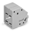 | 691412120006MB | SPEC | – | 6 Dateien | WR-TBL Series 412MB - 3.50 mm Screwless 45° Entry - 2.08 mm² Wires | 6 | Screwless | PCB | Nein | 14 to 20 (AWG) 2.08 to 0.518 (mm²) | – | – | – | – | – | – | -40 °C bis zu +105 °C | 3.5 | 22.5 | – | – | Karton | – | – | -40 °C up to +105 °C | – | – | – | – | – | 2 | – | – | – | – | – | – | 45° | |
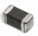 | 74279263 | SPEC | 9 Dateien | WE-CBF SMT-Ferrit | – | – | – | – | – | – | – | – | – | – | – | -55 °C bis zu +125 °C | – | 1.6 | 0.8 | 0.8 | – | – | 0603 | -55 °C up to +125 °C | – | – | – | 0.3 | – | 0.5 | – | 220 | 280 | 350 MHz | 1000 | 0.3 | Breitband | ||
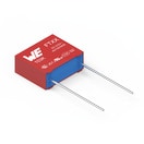 | 890334025027CS | SPEC | 8 Dateien | WCAP-FTXX Folienkondensatoren | – | Across the mains | – | – | – | 220 nF | 310 | X2 | 180 | 0.1 | 30 GΩ | -40 °C bis zu +105 °C | 15 | 18 | 6 | 11.5 | Karton | ±10% | Pitch 15 mm | -40 °C up to +105 °C | – | – | – | – | – | – | – | – | – | – | – | – | – | ||
| 890334025039CS | SPEC | 8 Dateien | WCAP-FTXX Folienkondensatoren | – | Across the mains | – | – | – | 470 nF | 310 | X2 | 220 | 0.1 | 21.28 GΩ | -40 °C bis zu +105 °C | 15 | 18 | 8 | 14 | Karton | ±10% | Pitch 15 mm | -40 °C up to +105 °C | – | – | – | – | – | – | – | – | – | – | – | – | – | ||
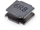 | 74404064330 | SPEC | 8 Dateien | WE-LQS SMT-Speicherdrossel | – | – | – | – | – | – | – | – | – | – | – | – | – | 6 | 6 | 4.5 | – | – | 6045 | -40 °C up to +125 °C | – | – | – | – | 33 | 1.8 | 2 | – | – | – | – | – | – | ||
 | 885012206027 | SPEC | 8 Dateien | WCAP-CSGP MLCCs 10 V(DC) | – | – | – | – | – | 2.2 µF | 10 | – | – | – | 0.05 GΩ | – | – | 1.6 | 0.8 | 0.8 | 7" Tape & Reel | ±10% | 0603 | -55 °C up to +125 °C | – | 10 | X7R Klasse II | 0.4 | – | – | – | – | – | – | – | – | – | ||
| 885012206056 | SPEC | 8 Dateien | WCAP-CSGP MLCCs 25 V(DC) | – | – | – | – | – | 330 pF | 25 | – | – | – | 10 GΩ | – | – | 1.6 | 0.8 | 0.8 | 7" Tape & Reel | ±10% | 0603 | -55 °C up to +125 °C | – | 3.5 | X7R Klasse II | 0.4 | – | – | – | – | – | – | – | – | – | ||
| 885012206076 | SPEC | 8 Dateien | WCAP-CSGP MLCCs 25 V(DC) | – | – | – | – | – | 1 µF | 25 | – | – | – | 0.5 GΩ | – | – | 1.6 | 0.8 | 0.8 | 7" Tape & Reel | ±10% | 0603 | -55 °C up to +125 °C | – | 10 | X7R Klasse II | 0.4 | – | – | – | – | – | – | – | – | – | ||
| 885012206083 | SPEC | 8 Dateien | WCAP-CSGP MLCCs 50 V(DC) | – | – | – | – | – | 1 nF | 50 | – | – | – | 10 GΩ | – | – | 1.6 | 0.8 | 0.8 | 7" Tape & Reel | ±10% | 0603 | -55 °C up to +125 °C | – | 2.5 | X7R Klasse II | 0.4 | – | – | – | – | – | – | – | – | – | ||
| 885012206095 | SPEC | 8 Dateien | WCAP-CSGP MLCCs 50 V(DC) | – | – | – | – | – | 100 nF | 50 | – | – | – | 5 GΩ | – | – | 1.6 | 0.8 | 0.8 | 7" Tape & Reel | ±10% | 0603 | -55 °C up to +125 °C | – | 3 | X7R Klasse II | 0.4 | – | – | – | – | – | – | – | – | – | ||
| 885012007034 | SPEC | 8 Dateien | WCAP-CSGP MLCCs 25 V(DC) | – | – | – | – | – | 100 pF | 25 | – | – | – | 10 GΩ | – | – | 2 | 1.25 | 0.6 | 7" Tape & Reel | ±5% | 0805 | -55 °C up to +125 °C | 1000 | – | NP0 Klasse I | 0.5 | – | – | – | – | – | – | – | – | – | ||
| 885012007051 | SPEC | 8 Dateien | WCAP-CSGP MLCCs 50 V(DC) | – | – | – | – | – | 10 pF | 50 | – | – | – | 10 GΩ | – | – | 2 | 1.25 | 0.6 | 7" Tape & Reel | ±5% | 0805 | -55 °C up to +125 °C | 600 | – | NP0 Klasse I | 0.5 | – | – | – | – | – | – | – | – | – | ||
| 885012207076 | SPEC | 7 Dateien | WCAP-CSGP MLCCs 25 V(DC) | – | – | – | – | – | 470 nF | 25 | – | – | – | 1.1 GΩ | – | – | 2 | 1.25 | 1.25 | 7" Tape & Reel | ±10% | 0805 | -55 °C up to +125 °C | – | 3.5 | X7R Klasse II | 0.5 | – | – | – | – | – | – | – | – | – | ||
| 885012207078 | SPEC | 7 Dateien | WCAP-CSGP MLCCs 25 V(DC) | – | – | – | – | – | 1 µF | 25 | – | – | – | 0.5 GΩ | – | – | 2 | 1.25 | 1.25 | 7" Tape & Reel | ±10% | 0805 | -55 °C up to +125 °C | – | 5 | X7R Klasse II | 0.5 | – | – | – | – | – | – | – | – | – | ||
| 885012207086 | SPEC | 8 Dateien | WCAP-CSGP MLCCs 50 V(DC) | – | – | – | – | – | 1 nF | 50 | – | – | – | 10 GΩ | – | – | 2 | 1.25 | 0.8 | 7" Tape & Reel | ±10% | 0805 | -55 °C up to +125 °C | – | 2.5 | X7R Klasse II | 0.5 | – | – | – | – | – | – | – | – | – | ||
| 885012207092 | SPEC | 8 Dateien | WCAP-CSGP MLCCs 50 V(DC) | – | – | – | – | – | 10 nF | 50 | – | – | – | 10 GΩ | – | – | 2 | 1.25 | 0.8 | 7" Tape & Reel | ±10% | 0805 | -55 °C up to +125 °C | – | 2.5 | X7R Klasse II | 0.5 | – | – | – | – | – | – | – | – | – | ||
| 885012207093 | SPEC | 8 Dateien | WCAP-CSGP MLCCs 50 V(DC) | – | – | – | – | – | 15 nF | 50 | – | – | – | 10 GΩ | – | – | 2 | 1.25 | 0.8 | 7" Tape & Reel | ±10% | 0805 | -55 °C up to +125 °C | – | 2.5 | X7R Klasse II | 0.5 | – | – | – | – | – | – | – | – | – | ||
| 885012207094 | SPEC | 8 Dateien | WCAP-CSGP MLCCs 50 V(DC) | – | – | – | – | – | 22 nF | 50 | – | – | – | 10 GΩ | – | – | 2 | 1.25 | 0.8 | 7" Tape & Reel | ±10% | 0805 | -55 °C up to +125 °C | – | 2.5 | X7R Klasse II | 0.5 | – | – | – | – | – | – | – | – | – | ||
| 885012207096 | SPEC | 8 Dateien | WCAP-CSGP MLCCs 50 V(DC) | – | – | – | – | – | 47 nF | 50 | – | – | – | 10 GΩ | – | – | 2 | 1.25 | 0.8 | 7" Tape & Reel | ±10% | 0805 | -55 °C up to +125 °C | – | 2.5 | X7R Klasse II | 0.5 | – | – | – | – | – | – | – | – | – | ||
| 885012207098 | SPEC | 8 Dateien | WCAP-CSGP MLCCs 50 V(DC) | – | – | – | – | – | 100 nF | 50 | – | – | – | 5 GΩ | – | – | 2 | 1.25 | 0.8 | 7" Tape & Reel | ±10% | 0805 | -55 °C up to +125 °C | – | 2.5 | X7R Klasse II | 0.5 | – | – | – | – | – | – | – | – | – | ||
| 885012207100 | SPEC | 8 Dateien | WCAP-CSGP MLCCs 50 V(DC) | – | – | – | – | – | 220 nF | 50 | – | – | – | 2.3 GΩ | – | – | 2 | 1.25 | 1.25 | 7" Tape & Reel | ±10% | 0805 | -55 °C up to +125 °C | – | 3 | X7R Klasse II | 0.5 | – | – | – | – | – | – | – | – | – | ||
| 885012208089 | SPEC | 8 Dateien | WCAP-CSGP MLCCs 50 V(DC) | – | – | – | – | – | 220 nF | 50 | – | – | – | 2.3 GΩ | – | – | 3.2 | 1.6 | 0.95 | 7" Tape & Reel | ±10% | 1206 | -55 °C up to +125 °C | – | 2.5 | X7R Klasse II | 0.6 | – | – | – | – | – | – | – | – | – | ||
| 750315757 | SPEC | – | – | Power Inductor | – | – | – | – | – | – | – | – | – | – | – | – | – | – | – | – | – | – | – | – | – | – | – | – | – | – | – | – | – | – | – | – | – | ||
| 750315759 | SPEC | – | – | PFC Inductor | – | – | – | – | – | – | – | – | – | – | – | – | – | – | – | – | – | – | – | – | – | – | – | – | – | – | – | – | – | – | – | – | – | ||
| 750315879 | SPEC | – | – | Flyback Transformer | – | – | – | – | – | – | – | – | – | – | – | – | – | – | – | – | – | – | – | – | – | – | – | – | – | – | – | – | – | – | – | – | – |
| Muster |
|---|
| Artikel Nr. | Datenblatt | Simulation | Downloads | Produktserie | Pins | Anwendung | PCB/Kabel/Panel | Modularity | Wire Section | C | VR (V (AC)) | Sicherheitsklasse | dV/dt (V/µs) | DF @ 1 kHz (%) | RISO | Betriebstemperatur | Raster (mm) | L (mm) | W (mm) | H (mm) | Verpackung | Tol. C | Bauform | Betriebstemperatur | Q (%) | DF (%) | Keramiktyp | Fl (mm) | L (µH) | IR (A) | ISAT (A) | Z @ 100 MHz (Ω) | Zmax (Ω) | Testbedingung Zmax | IR 2 (mA) | RDC max. (Ω) | Typ | Muster |
|---|