Details
| Topologie | Sperrwandler |
| Eingangsspannung | 9-18 V |
| Schaltfrequenz | 80-360 kHz |
| Ausgang 1 | -5 V / 0.24 A |
| Ausgang 2 | 20 V / 0.24 A |
| IC-Revision | G |
Beschreibung
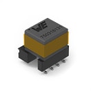
This reference design presents an extremely compact auxiliary power supply with a combined output power up to 6 W. Three different isolated bipolar output voltages are provided: +15 V / -4 V, +19 V / -4 V and +20 V / -5 V. The design is optimized for driving high-voltage SiC-MOSFET and IGBT discrete devices as well as power modules in high-power converters, and can be easily integrated in the gate driver system. The extremely low interwinding capacitance of the WE-AGDT transformers down to 7 pF helps to achieve high CMTI rating (Common-Mode Transient Immunity). This enables fast switching speeds which can yield efficiency and power density gains, as increasingly required in trending applications in e-mobility,renewable energy or industrial automation.
Eigenschaften
- Small size(Var.A: 27 mm x 14 mm x 14 mm) (Var.B: 40 mm x 14 mm x 13 mm)
- 4 kV primary-secondary isolation
- Only 7 pF typ. parasitic capacitance enabling high CMTI
- PSR Flyback topology with LT8302 (ADI Power by Linear)
- Load/line regulation less than 1 % typ.
- Up to 88 % peak efficiency (86 % at 6 W)
- Standard and AEC-Q qualified component assembly variants
- Two PCB Layout Variants (2-layer and 4-layer)
Typische Anwendungen
- Renewable energy: Solar inverters
- Switch-mode power supplies with SiC MOSFETs
- E-mobility: Electric Powertrain
- Industrial drives: AC motor inverter
- On-board and Off-board battery chargers
Weiterführende Informationen
Artikeldaten
| Artikel Nr. | Datenblatt | Simulation | Downloads | Status | Produktserie | C | Tol. C | VR (V (DC)) | Bauform | Betriebstemperatur | DF (%) | RISO | Keramiktyp | L (mm) | W (mm) | H (mm) | Fl (mm) | Verpackung | Vin (V) | VOut1 (V) | VOut2 (V) | PO (W) | CWW 1 (pF) | L (µH) | ISAT (A) | fswitch (kHz) | n | Version | IC-Referenz | Muster | |
|---|---|---|---|---|---|---|---|---|---|---|---|---|---|---|---|---|---|---|---|---|---|---|---|---|---|---|---|---|---|---|---|
| 885012207102 | SPEC | 9 Dateien | Aktiv i| Produktion ist aktiv. Erwartete Lebenszeit: >10 Jahre. | WCAP-CSGP MLCCs 50 V(DC) | 470 nF | ±10% | 50 | 0805 | -55 °C up to +125 °C | 3 | 1.1 GΩ | X7R Klasse II | 2 | 1.25 | 1.25 | 0.5 | 7" Tape & Reel | – | – | – | – | – | – | – | – | – | – | – | |||
| 885012207103 | SPEC | 9 Dateien | Aktiv i| Produktion ist aktiv. Erwartete Lebenszeit: >10 Jahre. | WCAP-CSGP MLCCs 50 V(DC) | 1 µF | ±10% | 50 | 0805 | -55 °C up to +125 °C | 10 | 0.1 GΩ | X7R Klasse II | 2 | 1.25 | 1.25 | 0.5 | 7" Tape & Reel | – | – | – | – | – | – | – | – | – | – | – | |||
| 885012108022 | SPEC | 9 Dateien | Aktiv i| Produktion ist aktiv. Erwartete Lebenszeit: >10 Jahre. | WCAP-CSGP MLCCs 50 V(DC) | 10 µF | ±10% | 50 | 1206 | -55 °C up to +85 °C | 10 | 0.005 GΩ | X5R Klasse II | 3.2 | 1.6 | 1.6 | 0.6 | 7" Tape & Reel | – | – | – | – | – | – | – | – | – | – | – | |||
 | 750319496 | SPEC | 9 Dateien | Aktiv i| Produktion ist aktiv. Erwartete Lebenszeit: >10 Jahre. | WE-AGDT Auxiliary Gate Drive Transformer | – | – | – | EP7 | -40 °C up to +130 °C | – | – | – | 11.3 | 10.95 | 11.94 | – | – | 9 - 18 | 20 | 5 | 6 | 7.3 | 7 | 4.5 | 350 | 1.8:3.6:1 | Flyback | LT8302 |
| Artikel Nr. | Datenblatt | Simulation | |
|---|---|---|---|
| 885012207102 | SPEC | ||
| 885012207103 | SPEC | ||
| 885012108022 | SPEC | ||
 | 750319496 | SPEC |
| Muster |
|---|
| Artikel Nr. | Datenblatt | Simulation | Downloads | Status | Produktserie | C | Tol. C | VR (V (DC)) | Bauform | Betriebstemperatur | DF (%) | RISO | Keramiktyp | L (mm) | W (mm) | H (mm) | Fl (mm) | Verpackung | Vin (V) | VOut1 (V) | VOut2 (V) | PO (W) | CWW 1 (pF) | L (µH) | ISAT (A) | fswitch (kHz) | n | Version | IC-Referenz | Muster |
|---|


