Wide range of applications
Rigid-flex printed circuit boards, like many other technologies, were originally developed for military and aerospace applications. However, the production of RIGID.flex has changed from a somewhat handcrafted character to a largely automated series production, not least due to the introduced standardizations of the technology and also the advances in plant and process technology. Rigid-flex printed circuit boards can now be found in all industries and applications where miniaturization and reliability are important. One or more flexible polyimide foils, continuously pressed into the entire structure, connect the rigid parts and thus replace cables and connectors in the tightest of spaces.
We would be happy to help you create your printed circuit boards in a design that is optimal for you.
Please contact us!
Advantages of Würth Elektronik RIGID.flex technology
RIGID.flex printed circuit boards are characterized by a wide range of applications.
They are suitable for:
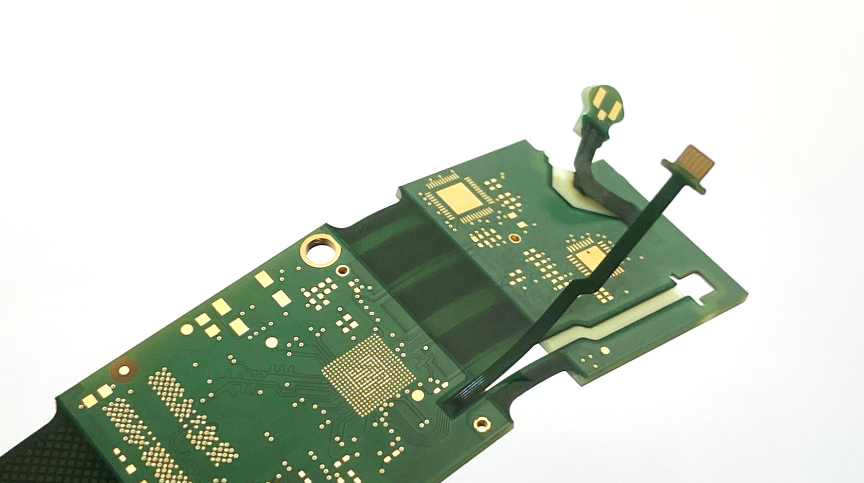
RIGID.flex in an USB3 industrial camera
Relevant parameters for production-ready PCB design
Modern printed circuit board solutions are more than just connecting elements. They are the key to progress in electronics. With this in mind, we actively support our customers in development and also offer our own system solutions with electronic functions.
The RIGID.flex design rules include all the important parameters you need to make your project successful:
In our design guide you will find an overview of all variants of our flex solutions. In addition, our specialists have summarized valuable design tips for you here. This will help you bring your application to success reliably and safely.
Get started with your layout faster thanks to standardized stackups
With these stackups, you automatically use market-customary and cost-optimized standards and avoid expensive custom builds. In addition, high-quality and cost-effective production with shorter delivery times is made possible because stock materials are used and standardized production processes are followed.
Here you will find our standard layer lay-ups for RIGID.flex in digital form for import into your EDA software and as PDF.
Basically all layouts are designed according to IPC-2223 Use A (Flex-to-install).
How can the space in the housing and layout on your PCB be optimally used with regard to miniaturization?
We have the solution: By combining HDI microvia technology and RIGID.flex, you can alleviate tight spaces.
Microvias, filled holes and thus a clever fanout of BGA footprints saves a lot of space. RIGID.flex technology can also eliminate footprints for connectors and enable the circuit to be folded into the housing to save space.
RIGID.flex and HDI microvia
Take a look at the recordings or the presentations of the webinars:
"Miniaturization to the power of two: Combine the advantages of RIGID.flex and HDI on your PCB! - Part 1"
"Miniaturization to the power of two: Combine the advantages of RIGID.flex and HDI on your PCB! - Part 2"
Webinar "Miniaturization to the power of two: Combine the advantages of RIGID.flex and HDI on your PCB! - Part 1"
Advantages of Würth Elektronik rigid-flexible PCBs
RIGID.flex PCBs
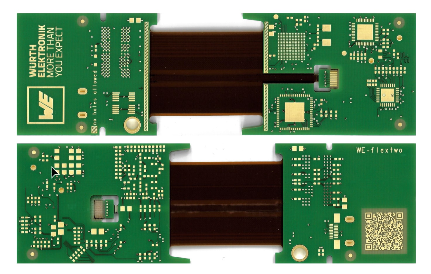
Our RIGID.flex physical PCB sample WE.flextwo shows you the many possibilities of this PCB technology with internal flex layers. Slot and key elements enable mechanical constructions with fixing options for the rigid parts to each other. Non-glued lift-off areas and laser cuts offer a wide range of mechatronic options for flex technology. Customized stackups enable impedance control, HDI design and dynamic bending.
Our RIGID.flex physical PCB sample WE.flexone shows you the diverse mechatronic possibilities of this PCB technology with external flex layers. This makes the difference between one and two copper layers in the two flex areas literally tangible. In addition, the different coatings of the flex areas can be compared with both flexible solder resist and coverlay. The sample shows a clever form of the popular ZIF contact and a flexibly connected high-frequency connector. A detachable lift-off area stimulates the senses and can trigger new product ideas.
Rigid-flex printed circuit boards often differ not only in their application-specific design but also in the stackup and coating of the flex areas. While the rigid areas are covered with a standard green solder resist, as with rigid PCBs, two different coatings are used for the flexible areas: flexible solder resist, or flex mask for short, and Coverlay.
But: What exactly differentiates the two options and when is a choice actually possible?
Learn more in this webinar about
We continue our series "PCB Production". The second part on RIGID.flex technology is intended as an introduction to the production of rigid-flex PCBs and covers constructions with internal flex layers.
In this webinar you will learn more about:
The first part on RIGID.flex technology is intended as an introduction to the production of rigid-flex PCBs and covers constructions with one or two external flex layers.
This webinar series teaches the basics of PCB production.
In this webinar you will learn more about:
Rigid-flex technology is generally regarded as a problem solver for special challenges in terms of miniaturization, reliability, signal integrity and system cost reduction. For the contemporary variant with two external flex layers, we will present these key features for the design of modern electronic systems in detail and show how easy it is to use. The webinar is rounded off with corresponding application examples.
Where system miniaturization is king and rapid or weak signals must be transmitted safely in critical environments, rigid-flex technology is often used. The webinar shows the advantages rigid-flex can offer to your system and the most modern ways of calculation, measurement and documentation of impedances, both in theory and in practical examples. Instructions and recommendations for best practice complete the webinar.
The USB specification includes requirements that affect the circuit board design and system interconnect cables. The use of the flex-rigid technology in combination with HDI offers the possibility of miniaturization and replaces the complex cabling between the modules. In this webinar, we will show you how to develop miniaturized USB applications using flex-rigid circuit boards. We will also highlight the advantages this all in one solutions provides for the overall system.
Already in the design phase, the course is set for the success of an electronic system. Even with careful planning and adhering to the design rules, mistakes are creeping in, which must be avoided.
In this webinar we show you:
You apply flex-rigid designs or have just started ? Maybe you are facing a number of challenges to tackle? Either in terms of:
Flex or semiflex? Polyimide or FR4? Interior or exterior flexible layer? With or without coverlay? You can find answers to these with examples in the new design guide for STARR.flex printed circuit boards. Thus you can reliably and securely make your application a success. We have outlined the most important parameters and most valuable design tips for you and explain these during the webinar.
Würth Elektronik´s 'Flex solutions' design guide provides an overview about the different variants as well as selection criteria and real examples. The approach of interdisciplinary cooperation in developments of flex-rigid designs is shown.
Drying before soldering is mandatory!
Flexible and rigid-flex printed circuit boards with polyimide are hygroscopic, i.e. they absorb moisture from the air even under normal room conditions. A dried polyimide film, for example, will have reached its moisture saturation level again after just a few hours. During the soldering process, the absorbed moisture can evaporate explosively, resulting in damage due to delamination, bubbling, tearing, etc. The original packaging is not moisture-proof.
The drying process must be qualified by the processor, the drying recommendations serve only as an approximate empirical value. Read our detailed drying specification here.
To facilitate and optimize the drying process, you can use our planning sheet for support.
Did you know that your PCB design is of great importance in this context? Learn more about the background and qualification of a suitable drying process.
A detailed Application Note "Physics of humidity & process of drying printed circuit boards" can be found here.
You also have the option to re-watch our webinar "Moisture in Printed Circuit Boards - developing an efficient drying process" or download the associated webinar presentation.
For static applications (IPC-2223 Use A – „flex-to-install“) or dynamical bending applications with little number of bending cycles or uncritical bending conditions ED copper (Electro-Deposited) is standard. RA copper (Rolled-Annealed) is used in dynamic applications (IPC-2223 Use B – „dynamical bending“), applications with several billions of bending cycles are known.
Please note:
No! FR4 materials have PTI / CTI level 3 up to 0 depending on the product (i.e. Nanya NP140 – CTI3 / NPG – CTI 2 / Panasonic R-1655W – CTI 1, just to list some options at least)
But polyimide, i.e. DuPont Pyralux AP or Panasonic R-F77x only has CTI level 4.
On the other hand almost all designs do not have free copper on the flex layer without a barrier in between like solder mask or coverlay. In addition, in case of flex inside the stackup all copper is completely covered by rigid material in the rigid sections or coverlay in the flexible sections.
Referring to the following table: FR4 dependent on type is then II or IIIa, but polyimide is IIIb.
Yes, many USB3 cameras use RIGID.flex circuit boards (USB3.1 Gen.2 supports a data rate of 10 Gbps). Important for this is a carefully tuned design with specified impedances. The USB3 specification requires differential lines with 90 Ohm characteristic impedance. We can calculate the necessary design parameters for you, suitable for an adapted layer stack. Usually polyimide cores with a thickness of 75µm or 100µm are used.
Rigid-flex technology offers the following advantages for high data rates:
For low temperatures, there are no specifications or limitations on the base materials used for rigid-flex PCBs. Our flex-rigid technology has been tested by UL according "Standard UL796 F Item 5.10 Cold Bend Test" and has passed these tests at -20°C.
In general there is no difference to rigid circuit boards. The values are defined in IPC-6013, Table 3-11 and dependant from IPC-class specification.
For example: according IPC class 2 up to 90° breakout of hole from land is allowed, for IPC class 3 the annular ring has to be minimum 50µm for external layers and 25µm for internal layers. The use of teardrops basically improves the manufacturability, see Figure 3-6.
Flexible base material Polyimide is available with different copper layer thicknesses. The standard thickness is 18 µm and goes up to nominal 70 µm. Due to the machining processes these thicknesses change, the tolerances according to IPC-6013 for inner layers apply.
Note: For plated outer layers IPC-6013C Table 3-19 applies.
Yes! Würth Elektronik has several types UL listed. All types have the flammability class according to UL94 (V-0 or V-1), some types have a so-called "full recognition" and are additionally listed with the parameters MOT, CTI and DSR marking.
The requirements regarding UL are derived from the UL standards for the UL category applicable to the product (Guidelines, UL certification documentation: "Section General" or as "critical components" in the "Description").
For many applications a flammability class V-1 according to UL94 is sufficient.
Contact us