LTSpice files
Characteristics
- Test voltage of 6400 VDC / 1 min.
- Construction: reinforced insulation
- Up to 1500 VDC working voltage
- Integrated filter chokes for common mode interference suppression
- Supports serial daisy chain isoSPI and SPI
- Available in different footprints
- Versions with low profile
- Operating temperature: -40 °C up to +125 °C
Applications
- Energy Storage systems
- Uninterrupted Power Supply (UPS)
- E-bikes, E-scooters
- Isolation of industrial interfaces
Products
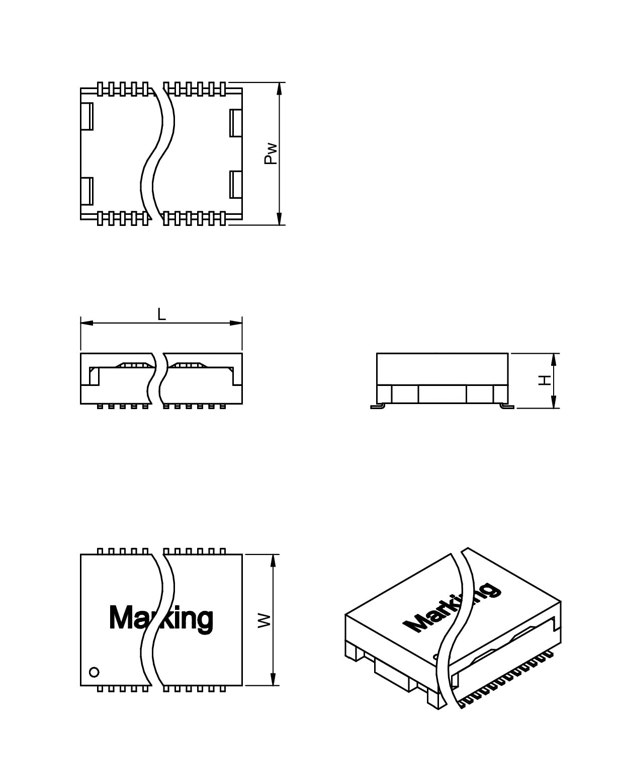
| Order Code | Datasheet | Downloads | Status | Ports | VT DC (V (DC)) | Working Voltage (V (DC)) | Cr (mm) | L (mm) | W (mm) | H (mm) | Samples | |
|---|---|---|---|---|---|---|---|---|---|---|---|---|
 | 74941300 | SPEC | 9 files | Active i| Production is active. Expected lifetime: >10 years. | 1 | 4300 | 1000 | 6 | 7.6 | 9.5 | 5.5 | |
 | 74941301 | SPEC | 9 files | Active i| Production is active. Expected lifetime: >10 years. | 1 | 4300 | 1000 | 5 | 7.6 | 9.5 | 5.5 | |
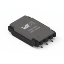 | 74941302 | SPEC | 9 files | Active i| Production is active. Expected lifetime: >10 years. | 1 | 4300 | 1000 | 10 | 9.5 | 15.4 | 3.45 | |
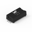 | 74942402 | SPEC | 7 files | Active i| Production is active. Expected lifetime: >10 years. | 1 | 6400 | 1500 | 15 | 12.5 | 28 | 7.3 | |
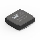 | 74942300 | SPEC | 9 files | Active i| Production is active. Expected lifetime: >10 years. | 2 | 4300 | 1000 | 10 | 15.1 | 14.7 | 4.75 | |
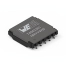 | 74942301 | SPEC | 9 files | Active i| Production is active. Expected lifetime: >10 years. | 2 | 4300 | 1000 | 10 | 15.1 | 14.9 | 3.45 | |
 | 74942302 | SPEC | 9 files | Active i| Production is active. Expected lifetime: >10 years. | 2 | 4300 | 1000 | 10 | 15.1 | 15.4 | 3.45 | |
 | 74942400 | SPEC | 7 files | Active i| Production is active. Expected lifetime: >10 years. | 2 | 6400 | 1500 | 15 | 15.45 | 27.85 | 4.85 | |
 | 74942401 | SPEC | 7 files | Active i| Production is active. Expected lifetime: >10 years. | 2 | 6400 | 1500 | 15 | 15.45 | 27.85 | 4.85 |
| Order Code | Datasheet | |
|---|---|---|
 | 74941300 | SPEC |
 | 74941301 | SPEC |
 | 74941302 | SPEC |
 | 74942402 | SPEC |
 | 74942300 | SPEC |
 | 74942301 | SPEC |
 | 74942302 | SPEC |
 | 74942400 | SPEC |
 | 74942401 | SPEC |
| Samples |
|---|
| Order Code | Datasheet | Downloads | Status | Ports | VT DC (V (DC)) | Working Voltage (V (DC)) | Cr (mm) | L (mm) | W (mm) | H (mm) | Samples |
|---|
Transformer for Battery Management Systems With Integrated Common Mode Choke
Transformer for Battery Management Systems With Integrated Common Mode Choke
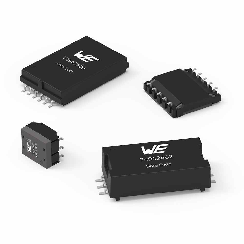
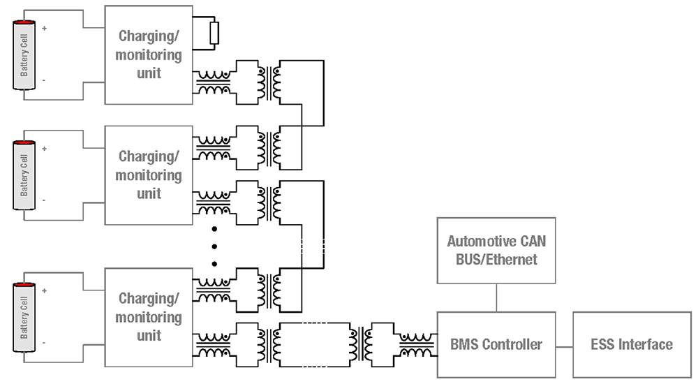
The WE-BMS series isolates the serial-connected components of the battery pack and the following BMS controllers from each other, suppressing any voltage differences and EMI that may occur. The design from Würth Elektronik provides a much larger physical creepage distance as opposed to other competitors, following market requirements for this kind of applications.
By maintaining the physical distance through the innovative design regardless of coated traces, high system safety and reliability can be achieved through special robustness against dryness or heat. Fully insulated wires are used for flat design and even better isolation properties.
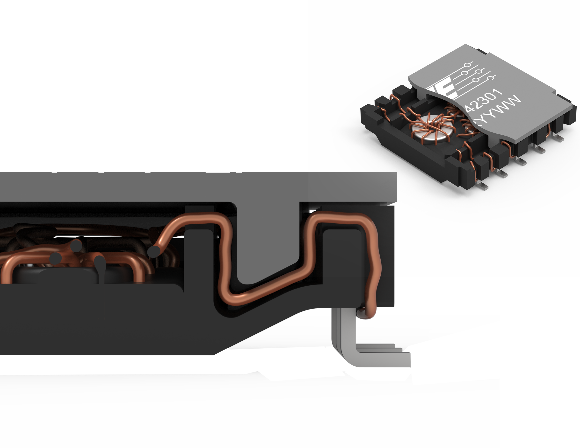
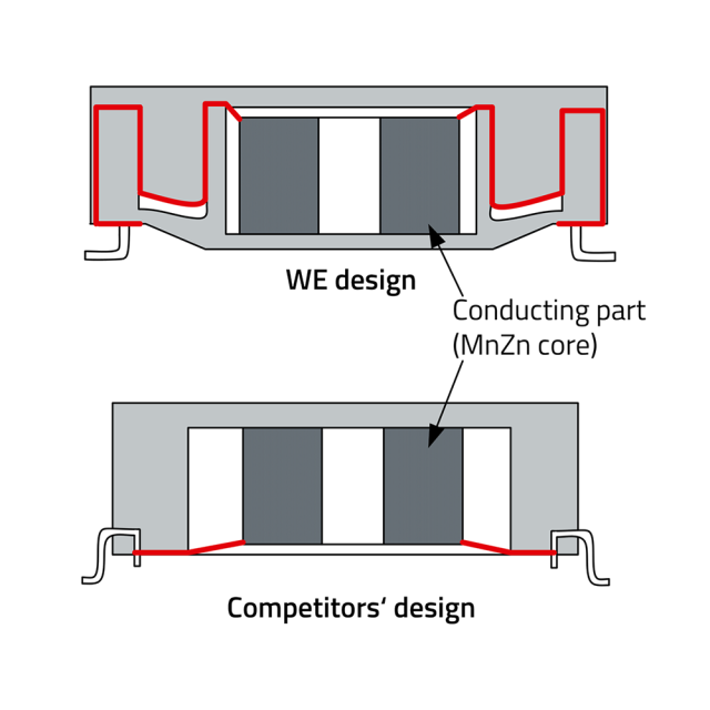
Thanks to the innovative construction, a larger physical creepage distance can be achieved with the same size as with the conventional design.
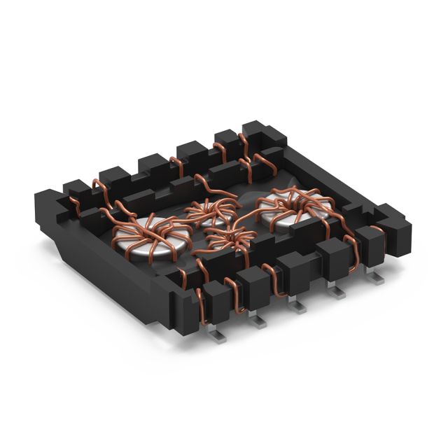
The included transformers and common mode chokes ensure BMS isolation and suppress electromagnetic interference for reliable signal transmission.
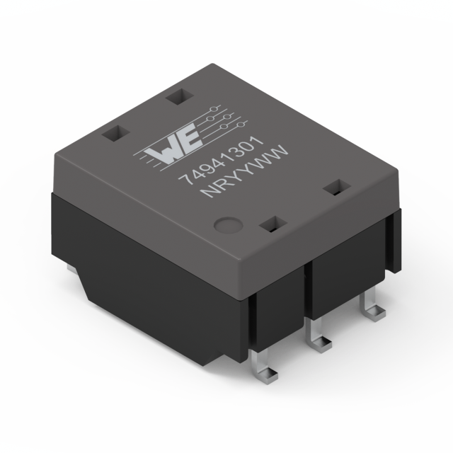
The WE-BMS series supports serial Daisy Chain, isoSPI, SPI and other signal isolations. Single and dual transformer for one or two channels are available.
BMS Layout Guidelines
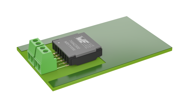
The signal lines should be kept as short as possible and the transformer should be as close as possible to the isoSPI cable connector. A distance of <2 cm is suggested.
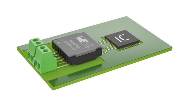
IC should be placed between 1-2 cm from the transformer to avoid magnetic coupling.
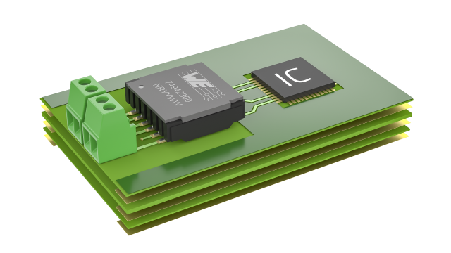
For four-layer or multilayer PCBs, the area around the BMS traces, the BMS socket and the transformer should be exposed in all layers. The distance around this area to copper surfaces and traces should be at least 4 mm, depending on the system working voltage.
From the Smallest to the Largest Applications
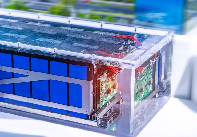
The transformers with 1000 VDC working voltage are suitable for smaller energy storage systems such as consumer energy storage and for applications with lower voltages such as 600 VDC
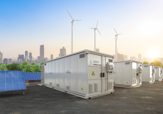
BMS transformers with a working voltage of 1500 VDC and a test voltage of 6400 VDC are available for applications with large battery packs, such as in energy storage systems for solar and wind farms.
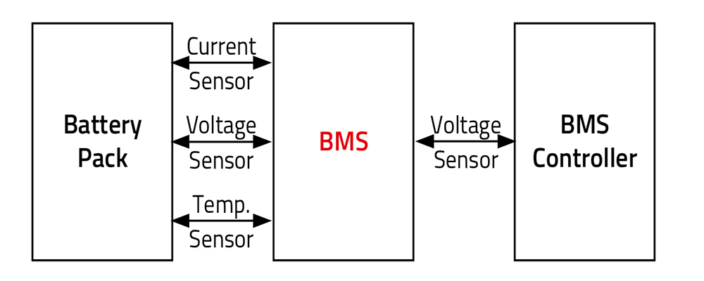
A BMS is an electronic system that manages a rechargeable battery with the goal to make it safe and reliable.
Functions of a BMS:
- Protecting the battery from operating outside its safe operation area
- Monitoring its state of charge and state of health
- Calculating secondary data and reporting that data
- Controlling its environment
- Authenticating it and/or balancing it
The individual cells in a battery pack are connected in series as well as the following BMS controllers. Between the components or PCBs connected in series, voltage differences and electromagnetic interference can occur. A transformer can be used to insolate the components from each other and suppress EMI interference. Therefore, WE-BMS transformer supports the BMS isolation and EMI noise suppression for a safe and reliable operation.
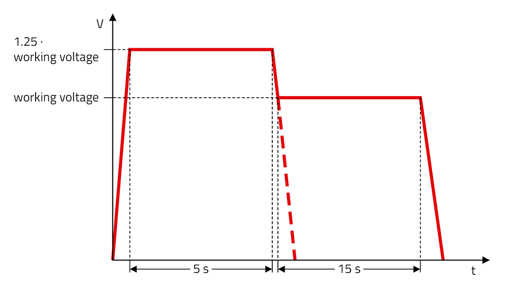
Partial discharges are localized dielectric breakdowns. Fixed insulation in which partial discharges occur during operation is not permitted in the long term.
To ensure the long term reliability of the insulation, Würth Elektronik carries out the partial discharge test in accordance with IEC 60664-1.
The test is passed if the quantity of partial discharges is below a limit value of 10 pC (pico coulomb).
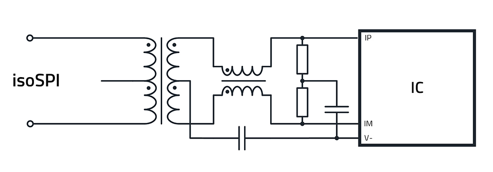
The Würth Elektronik product portfolio offers transformers with and without a center pin. In addition to the integrated common mode choke in the transformer module, the center pin contributes to the suppression of common mode interference. For this purpose, a bypass capacitor is connected to the center pin, which provides a low impedance ground connection for common mode interference and thus diverts it towards earth. This leads to an improvement in isoSPI performance. Please refer to the IC manufacturer's data sheet for the selection of capacitors.
