IC manufacturers (106)
- All manufacturers
 Analog Devices
 Infineon Technologies
 Microchip
 Onsemi
 Renesas
 ROHM
ROHM STMicroelectronics
 Texas Instruments
- 3peak incorporated (35)
- Ablic (23)
- Acco Semiconductor (1)
- Advanced Power (4)
- Allegro Microsystems (100)
- Alpha & Omega Semiconductor (37)
- AnalogySemi (3)
- AnDAPT Inc (204)
- Anpec (13)
- AXElite (2)
- Backward (6)
- Bright Power Semiconductor (1)
- Broadcom (46)
- Cambridge GaN Devices (18)
- Chipanalog Micro (10)
- Cologne Chips (1)
- Convenient Power (1)
- Dialog Semiconductor (12)
- Diodes Incorporated (257)
- Divimath (8)
- Elmos AG (1)
- EPC (146)
- e-Peas Semiconductors (1)
- Eta Solutions Co. Ltd. (9)
- GaN Systems (8)
- GaNPower (3)
- Giantec (1)
- Gosemicon (2)
- Gstek Wuxi (1)
- Helix Semiconductor (7)
- IKON (1)
- Indie Semiconductor (8)
- Innovision Semiconductor Inc (2)
- Intel (68)
- Inventchip Technology (3)
- ISSI (51)
- JoulWatt (20)
- KDPOF (3)
- Kinetic Technology (8)
- Lattice semiconductor Corporation (38)
- Littelfuse (1)
- Lumissil Microsystems (8)
- M3 Technology (M3Tek) (7)
- Macnica (22)
- Marvell Semiconductor (1)
- MaxLinear (181)
- Menlo Micro (1)
- MikroE (25)
- MindCet (2)
- Monolithic Power Systems (983)
- Navitas Semiconductor Inc (6)
- NewEdge Technologies, Inc. (1)
- Nexperia (268)
- Nisshinbo Micro Device Inc. (9)
- Nordic Semiconductor (1)
- Novosense Micro (1)
- NXP (343)
- O2 Micro International Ltd (10)
- On Bright (7)
- Panasonic (2)
- PN Junction Semiconductor (2)
- Power Integrations (117)
- Powermat (1)
- Pulsiv (19)
- Qorvo (99)
- Realsil SuRealsil(tek) Microelectronics (1)
- Richtek (297)
- Sanken Electric Co., Ltd. (16)
- Sckipio (6)
- Semtech (86)
- SG-Micro (58)
- SiFive (2)
- Silanna Semiconductor (9)
- Silergy Corporation (34)
- Silicon Laboratory Inc. (108)
- Silicontent Technology (59)
- Silvertel (59)
- Skycore Semiconductors (1)
- Skyworks (33)
- Southchip (18)
- Summit Wireless (1)
- Tagore Tech (7)
- Taiwan Semiconductor (1)
- TDK Corporation (1)
- Tempo Semiconductor (1)
- Torex (37)
- Toshiba (27)
- Transphorm (21)
- TransSIP (2)
- Union (21)
- uPI Semiconductor (2)
- Valens Semiconductor (31)
- VisIC (1)
- Wise Integration (3)
- Wolfspeed (23)
- Xilinx (22)
- XL Semiconductor (3)
- XYSemi (62)
Overview
| Topology | Power Factor Correction |
| Switching frequency | 120 kHz |
| IC revision | 1.1 |
Description
The compounded LSI of the Power Factor Correction (PFC) converter and Quasi-Resonant (QR) controller type DC/DC converter IC provides an optimum system for all products that include an electrical outlet. BM1C102F has a built in High Voltage starter circuit that tolerates 650V and X-Cap discharge function, and contributes to low power consumption and high speed start. The PFC part operates by Boundary Conduction Mode (BCM). It reduces the switching loss and the switching noise. Because of zero current detection (ZCD) by a resistance, this solution achieves no auxiliary winding and reduces external parts and the bias current. The DC/DC part operates by Quasi-Resonant Mode. This method enables soft switching and helps to keep the EMI low. With putting MOSFET for switching and current detection resistors as external devices, a higher freedom design is possible. This IC has double over voltage protection for the PFC output terminal. IC makes the standby power consumption low by the PFC ON/OFF control function. The IC includes various protect functions such as VCC over voltage protection, external latch protection, brown out protection, soft start function, per-cycle current limiter and over load protection.
Features
- PFC+QR Combo IC
- Built-in 650V tolerance start circuit
- VCC pin: under and over voltage protection
- Brown out function
- External latch terminal function
- PFC boundary conduction mode (voltage control)
- PFC Zero Cross Detection
- PFC variable max frequency
- PFC Dynamic & Static OVP function
Typical applications
- Power Grids
More information
Products
Order Code | Datasheet | Simulation | Downloads | Status | Product series | Pins | Application | PCB/Cable/Panel | Modularity | Type | Wire Section | C | VR(V (AC)) | VR 2(V (DC)) | Safety Class | dV/dt(V/µs) | DF @ 1 kHz(%) | RISO | Pitch(mm) | L(mm) | W(mm) | H(mm) | Packaging | Tol. C | Size | Operating Temperature | Q | DF(%) | Ceramic Type | Fl(mm) | Endurance(h) | IRIPPLE(mA) | ILeak(µA) | Ø D(mm) | VRMS(V) | VDC(V) | VBR(V) | IPeak(A) | Wmax(J) | PDiss(W) | VDE Approval | L(µH) | IR(A) | RDC max.(Ω) | SamplesAvailability & Sample | |||||||||||||||||||||||||||||||||||||||||||||||||||||||||||||||||||||||||||||||||||||||||||||||||||||||||||||||||||||||||||||||||||||||||||||||||||||||||||||||||||||||||||||||||||||||||||||||||||||||||||||||||||||||||||||||||||||||||||||||||||||||||||||||||||||||||||||||||||||||||||||||||||||||||||||||||||||||||||||||||||||||||||||||||||||||||||||||||||||||||||||||||||||||||||||||||||||||||||||||||||||||||||||||||||||||||||||||||||||||||||||||||||||||||||||||||||||||||||||||||||||||||||||||||||||||||||||||||||||||||||||||||||||||||||||||||||||||||||||||||||||||||||||||||||||||||||||||||||||||||||||||||||||||||||||||||||||||||||||||||||||||||||||||||||||||||||||||||||||||||||||||||||||||||||||||||||||||||||||||||||||||||||||||||||||||||||||||||||||||||||||||||||||||||||||||||||||||||||||||||||||||||||||||||||||||||||||||||||||||||||||||||||||||||||||||||||||||||||||||||||||||||||||||||||||||||||||||||||||||||||||||||||||||||||||||||||||||||
|---|---|---|---|---|---|---|---|---|---|---|---|---|---|---|---|---|---|---|---|---|---|---|---|---|---|---|---|---|---|---|---|---|---|---|---|---|---|---|---|---|---|---|---|---|---|---|---|---|---|---|---|---|---|---|---|---|---|---|---|---|---|---|---|---|---|---|---|---|---|---|---|---|---|---|---|---|---|---|---|---|---|---|---|---|---|---|---|---|---|---|---|---|---|---|---|---|---|---|---|---|---|---|---|---|---|---|---|---|---|---|---|---|---|---|---|---|---|---|---|---|---|---|---|---|---|---|---|---|---|---|---|---|---|---|---|---|---|---|---|---|---|---|---|---|---|---|---|---|---|---|---|---|---|---|---|---|---|---|---|---|---|---|---|---|---|---|---|---|---|---|---|---|---|---|---|---|---|---|---|---|---|---|---|---|---|---|---|---|---|---|---|---|---|---|---|---|---|---|---|---|---|---|---|---|---|---|---|---|---|---|---|---|---|---|---|---|---|---|---|---|---|---|---|---|---|---|---|---|---|---|---|---|---|---|---|---|---|---|---|---|---|---|---|---|---|---|---|---|---|---|---|---|---|---|---|---|---|---|---|---|---|---|---|---|---|---|---|---|---|---|---|---|---|---|---|---|---|---|---|---|---|---|---|---|---|---|---|---|---|---|---|---|---|---|---|---|---|---|---|---|---|---|---|---|---|---|---|---|---|---|---|---|---|---|---|---|---|---|---|---|---|---|---|---|---|---|---|---|---|---|---|---|---|---|---|---|---|---|---|---|---|---|---|---|---|---|---|---|---|---|---|---|---|---|---|---|---|---|---|---|---|---|---|---|---|---|---|---|---|---|---|---|---|---|---|---|---|---|---|---|---|---|---|---|---|---|---|---|---|---|---|---|---|---|---|---|---|---|---|---|---|---|---|---|---|---|---|---|---|---|---|---|---|---|---|---|---|---|---|---|---|---|---|---|---|---|---|---|---|---|---|---|---|---|---|---|---|---|---|---|---|---|---|---|---|---|---|---|---|---|---|---|---|---|---|---|---|---|---|---|---|---|---|---|---|---|---|---|---|---|---|---|---|---|---|---|---|---|---|---|---|---|---|---|---|---|---|---|---|---|---|---|---|---|---|---|---|---|---|---|---|---|---|---|---|---|---|---|---|---|---|---|---|---|---|---|---|---|---|---|---|---|---|---|---|---|---|---|---|---|---|---|---|---|---|---|---|---|---|---|---|---|---|---|---|---|---|---|---|---|---|---|---|---|---|---|---|---|---|---|---|---|---|---|---|---|---|---|---|---|---|---|---|---|---|---|---|---|---|---|---|---|---|---|---|---|---|---|---|---|---|---|---|---|---|---|---|---|---|---|---|---|---|---|---|---|---|---|---|---|---|---|---|---|---|---|---|---|---|---|---|---|---|---|---|---|---|---|---|---|---|---|---|---|---|---|---|---|---|---|---|---|---|---|---|---|---|---|---|---|---|---|---|---|---|---|---|---|---|---|---|---|---|---|---|---|---|---|---|---|---|---|---|---|---|---|---|---|---|---|---|---|---|---|---|---|---|---|---|---|---|---|---|---|---|---|---|---|---|---|---|---|---|---|---|---|---|---|---|---|---|---|---|---|---|---|---|---|---|---|---|---|---|---|---|---|---|---|---|---|---|---|---|---|---|---|---|---|---|---|---|---|---|---|---|---|---|---|---|---|---|---|---|---|---|---|---|---|---|---|---|---|---|---|---|---|---|---|---|---|---|---|---|---|---|---|---|---|---|---|---|---|---|---|---|---|---|---|---|---|---|---|---|---|---|---|---|---|---|---|---|---|---|---|---|---|---|---|---|---|---|---|---|---|---|---|---|---|---|---|---|---|---|---|---|---|---|---|---|---|---|---|---|---|---|---|---|---|---|---|---|---|---|---|---|---|---|---|---|---|---|---|---|---|---|---|---|---|---|---|---|---|---|---|---|---|---|---|---|---|---|---|---|---|---|---|---|---|---|---|---|---|---|---|---|---|---|---|---|---|---|---|---|---|---|---|---|---|---|---|---|---|---|---|---|---|---|---|---|---|---|---|---|---|---|---|---|---|---|---|---|---|---|---|---|---|---|---|---|---|---|---|---|---|---|---|---|---|---|---|---|---|---|---|---|---|---|---|---|---|---|---|---|---|---|---|---|---|---|---|---|---|---|---|---|---|---|---|---|---|---|---|---|---|---|---|---|---|---|---|---|---|---|---|---|---|---|---|---|---|---|---|---|---|---|---|---|---|
| Log in now to view availability and request availability forecasts. LOGIN | ||||||||||||||||||||||||||||||||||||||||||||||||||||||||||||||||||||||||||||||||||||||||||||||||||||||||||||||||||||||||||||||||||||||||||||||||||||||||||||||||||||||||||||||||||||||||||||||||||||||||||||||||||||||||||||||||||||||||||||||||||||||||||||||||||||||||||||||||||||||||||||||||||||||||||||||||||||||||||||||||||||||||||||||||||||||||||||||||||||||||||||||||||||||||||||||||||||||||||||||||||||||||||||||||||||||||||||||||||||||||||||||||||||||||||||||||||||||||||||||||||||||||||||||||||||||||||||||||||||||||||||||||||||||||||||||||||||||||||||||||||||||||||||||||||||||||||||||||||||||||||||||||||||||||||||||||||||||||||||||||||||||||||||||||||||||||||||||||||||||||||||||||||||||||||||||||||||||||||||||||||||||||||||||||||||||||||||||||||||||||||||||||||||||||||||||||||||||||||||||||||||||||||||||||||||||||||||||||||||||||||||||||||||||||||||||||||||||||||||||||||||||||||||||||||||||||||||||||||||||||||||||||||||||||||||||||||||||||||||||||||||||||||||||||||||||||||||||||||||||
 | SPECWR-TBL Series 2365 - 5.08 mm Horiz. Entry w. Rising Cage Clamp, 2, Rising Cage Clamp | Simulation– | Availability – | Downloads7 files | Status Activei| Production is active. Expected lifetime: >10 years. | Pins2 | ApplicationRising Cage Clamp | PCB/Cable/PanelPCB | ModularityYes | TypeHorizontal | Wire Section 12 to 30 (AWG) 3.31 to 0.0509 (mm²) | – | – | – | – | – | – | – | Pitch5.08 mm | Length10.16 mm | – | – | PackagingBox | – | – | Operating Temperature -30 °C up to +120 °C | – | – | – | – | – | – | – | – | – | – | – | – | – | – | – | – | Rated Current20 A | – | –Check availability | |||||||||||||||||||||||||||||||||||||||||||||||||||||||||||||||||||||||||||||||||||||||||||||||||||||||||||||||||||||||||||||||||||||||||||||||||||||||||||||||||||||||||||||||||||||||||||||||||||||||||||||||||||||||||||||||||||||||||||||||||||||||||||||||||||||||||||||||||||||||||||||||||||||||||||||||||||||||||||||||||||||||||||||||||||||||||||||||||||||||||||||||||||||||||||||||||||||||||||||||||||||||||||||||||||||||||||||||||||||||||||||||||||||||||||||||||||||||||||||||||||||||||||||||||||||||||||||||||||||||||||||||||||||||||||||||||||||||||||||||||||||||||||||||||||||||||||||||||||||||||||||||||||||||||||||||||||||||||||||||||||||||||||||||||||||||||||||||||||||||||||||||||||||||||||||||||||||||||||||||||||||||||||||||||||||||||||||||||||||||||||||||||||||||||||||||||||||||||||||||||||||||||||||||||||||||||||||||||||||||||||||||||||||||||||||||||||||||||||||||||||||||||||||||||||||||||||||||||||||||||||||||||||||||||||||||||||||||||
 | SPECWR-TBL Series 2365 - 5.08 mm Horiz. Entry w. Rising Cage Clamp, 3, Rising Cage Clamp | Simulation– | Availability – | Downloads7 files | Status Activei| Production is active. Expected lifetime: >10 years. | Pins3 | ApplicationRising Cage Clamp | PCB/Cable/PanelPCB | ModularityYes | TypeHorizontal | Wire Section 12 to 30 (AWG) 3.31 to 0.0509 (mm²) | – | – | – | – | – | – | – | Pitch5.08 mm | Length15.24 mm | – | – | PackagingBox | – | – | Operating Temperature -30 °C up to +120 °C | – | – | – | – | – | – | – | – | – | – | – | – | – | – | – | – | Rated Current20 A | – | –Check availability | |||||||||||||||||||||||||||||||||||||||||||||||||||||||||||||||||||||||||||||||||||||||||||||||||||||||||||||||||||||||||||||||||||||||||||||||||||||||||||||||||||||||||||||||||||||||||||||||||||||||||||||||||||||||||||||||||||||||||||||||||||||||||||||||||||||||||||||||||||||||||||||||||||||||||||||||||||||||||||||||||||||||||||||||||||||||||||||||||||||||||||||||||||||||||||||||||||||||||||||||||||||||||||||||||||||||||||||||||||||||||||||||||||||||||||||||||||||||||||||||||||||||||||||||||||||||||||||||||||||||||||||||||||||||||||||||||||||||||||||||||||||||||||||||||||||||||||||||||||||||||||||||||||||||||||||||||||||||||||||||||||||||||||||||||||||||||||||||||||||||||||||||||||||||||||||||||||||||||||||||||||||||||||||||||||||||||||||||||||||||||||||||||||||||||||||||||||||||||||||||||||||||||||||||||||||||||||||||||||||||||||||||||||||||||||||||||||||||||||||||||||||||||||||||||||||||||||||||||||||||||||||||||||||||||||||||||||||||||
 | SPECWE-VD Disk Varistor, –, 230 VAC | Availability – | Downloads7 files | Status Activei| Production is active. Expected lifetime: >10 years. | Product seriesWE-VD Disk Varistor | – | Application230 VAC | – | – | – | – | – | – | – | – | – | – | – | – | Length16.5 mm | Width4.8 mm | Height20.5 mm | – | – | Size14 mm | Operating Temperature -40 °C up to +105 °C | – | – | – | – | – | – | – | Diameter16.5 mm | AC Operating Voltage320 V | DC Operating Voltage418 V | (Reverse) Breakdown Voltage510 V | (Reverse) Peak Pulse Current6000 A | Energy Absorption190 J | Power Dissipation0.6 W | VDE ApprovalYes | – | – | – | –Check availability | |||||||||||||||||||||||||||||||||||||||||||||||||||||||||||||||||||||||||||||||||||||||||||||||||||||||||||||||||||||||||||||||||||||||||||||||||||||||||||||||||||||||||||||||||||||||||||||||||||||||||||||||||||||||||||||||||||||||||||||||||||||||||||||||||||||||||||||||||||||||||||||||||||||||||||||||||||||||||||||||||||||||||||||||||||||||||||||||||||||||||||||||||||||||||||||||||||||||||||||||||||||||||||||||||||||||||||||||||||||||||||||||||||||||||||||||||||||||||||||||||||||||||||||||||||||||||||||||||||||||||||||||||||||||||||||||||||||||||||||||||||||||||||||||||||||||||||||||||||||||||||||||||||||||||||||||||||||||||||||||||||||||||||||||||||||||||||||||||||||||||||||||||||||||||||||||||||||||||||||||||||||||||||||||||||||||||||||||||||||||||||||||||||||||||||||||||||||||||||||||||||||||||||||||||||||||||||||||||||||||||||||||||||||||||||||||||||||||||||||||||||||||||||||||||||||||||||||||||||||||||||||||||||||||||||||||||||||||||
 | SPECWCAP-FTXX Film Capacitors, –, Across the mains | Availability – | Status Activei| Production is active. Expected lifetime: >10 years. | Product seriesWCAP-FTXX Film Capacitors | – | ApplicationAcross the mains | – | – | – | – | Capacitance220 nF | Rated Voltage310 V (AC) | Rated Voltage 2630 V (DC) | Safety ClassX2 | Rate of Voltage Rise180 V/µs | Dissipation Factor0.1 % | Insulation Resistance30 GΩ | Pitch15 mm | Length18 mm | Width6 mm | Height11.5 mm | PackagingCarton | Capacitance±10% | SizePitch: 15 mm | Operating Temperature -40 °C up to +105 °C | – | – | – | – | – | – | – | – | – | – | – | – | – | – | – | – | – | – | –Check availability | ||||||||||||||||||||||||||||||||||||||||||||||||||||||||||||||||||||||||||||||||||||||||||||||||||||||||||||||||||||||||||||||||||||||||||||||||||||||||||||||||||||||||||||||||||||||||||||||||||||||||||||||||||||||||||||||||||||||||||||||||||||||||||||||||||||||||||||||||||||||||||||||||||||||||||||||||||||||||||||||||||||||||||||||||||||||||||||||||||||||||||||||||||||||||||||||||||||||||||||||||||||||||||||||||||||||||||||||||||||||||||||||||||||||||||||||||||||||||||||||||||||||||||||||||||||||||||||||||||||||||||||||||||||||||||||||||||||||||||||||||||||||||||||||||||||||||||||||||||||||||||||||||||||||||||||||||||||||||||||||||||||||||||||||||||||||||||||||||||||||||||||||||||||||||||||||||||||||||||||||||||||||||||||||||||||||||||||||||||||||||||||||||||||||||||||||||||||||||||||||||||||||||||||||||||||||||||||||||||||||||||||||||||||||||||||||||||||||||||||||||||||||||||||||||||||||||||||||||||||||||||||||||||||||||||||||||||||||||||
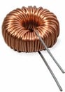 | SPECWE-FI Leaded Toroidal Line Choke, –, – | Simulation– | Availability – | Status Activei| Production is active. Expected lifetime: >10 years. | Product seriesWE-FI Leaded Toroidal Line Choke | – | – | – | – | – | – | – | – | – | – | – | – | – | – | Length25 mm | Width13.4 mm | – | – | – | – | Operating Temperature -40 °C up to +105 °C | – | – | – | – | – | – | – | – | – | – | – | – | – | – | – | Inductance470 µH | Rated Current3 A | DC Resistance0.11 Ω | –Check availability | |||||||||||||||||||||||||||||||||||||||||||||||||||||||||||||||||||||||||||||||||||||||||||||||||||||||||||||||||||||||||||||||||||||||||||||||||||||||||||||||||||||||||||||||||||||||||||||||||||||||||||||||||||||||||||||||||||||||||||||||||||||||||||||||||||||||||||||||||||||||||||||||||||||||||||||||||||||||||||||||||||||||||||||||||||||||||||||||||||||||||||||||||||||||||||||||||||||||||||||||||||||||||||||||||||||||||||||||||||||||||||||||||||||||||||||||||||||||||||||||||||||||||||||||||||||||||||||||||||||||||||||||||||||||||||||||||||||||||||||||||||||||||||||||||||||||||||||||||||||||||||||||||||||||||||||||||||||||||||||||||||||||||||||||||||||||||||||||||||||||||||||||||||||||||||||||||||||||||||||||||||||||||||||||||||||||||||||||||||||||||||||||||||||||||||||||||||||||||||||||||||||||||||||||||||||||||||||||||||||||||||||||||||||||||||||||||||||||||||||||||||||||||||||||||||||||||||||||||||||||||||||||||||||||||||||||||||||||||
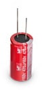 | SPECWCAP-ATG8 Aluminum Electrolytic Capacitors, –, – | Availability – | Status Activei| Production is active. Expected lifetime: >10 years. | Product seriesWCAP-ATG8 Aluminum Electrolytic Capacitors | – | – | – | – | – | – | Capacitance47 µF | Rated Voltage50 V (AC) | – | – | – | – | – | Pitch2.5 mm | Length11 mm | – | – | PackagingAmmopack | Capacitance±20% | – | – | – | Dissipation Factor10 % | – | – | Endurance 2000 | Ripple Current165 mA | Leakage Current23.5 µA | Diameter6.3 mm | – | – | – | – | – | – | – | – | – | – | –Check availability | ||||||||||||||||||||||||||||||||||||||||||||||||||||||||||||||||||||||||||||||||||||||||||||||||||||||||||||||||||||||||||||||||||||||||||||||||||||||||||||||||||||||||||||||||||||||||||||||||||||||||||||||||||||||||||||||||||||||||||||||||||||||||||||||||||||||||||||||||||||||||||||||||||||||||||||||||||||||||||||||||||||||||||||||||||||||||||||||||||||||||||||||||||||||||||||||||||||||||||||||||||||||||||||||||||||||||||||||||||||||||||||||||||||||||||||||||||||||||||||||||||||||||||||||||||||||||||||||||||||||||||||||||||||||||||||||||||||||||||||||||||||||||||||||||||||||||||||||||||||||||||||||||||||||||||||||||||||||||||||||||||||||||||||||||||||||||||||||||||||||||||||||||||||||||||||||||||||||||||||||||||||||||||||||||||||||||||||||||||||||||||||||||||||||||||||||||||||||||||||||||||||||||||||||||||||||||||||||||||||||||||||||||||||||||||||||||||||||||||||||||||||||||||||||||||||||||||||||||||||||||||||||||||||||||||||||||||||||||||
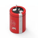 | SPECWCAP-AIG5 Aluminum Electrolytic Capacitors, –, – | Availability – | Status Activei| Production is active. Expected lifetime: >10 years. | Product seriesWCAP-AIG5 Aluminum Electrolytic Capacitors | – | – | – | – | – | – | Capacitance220 µF | Rated Voltage450 V (AC) | – | – | – | – | – | Pitch10 mm | Length45 mm | – | – | PackagingTray | Capacitance±20% | Size25.0 x 45.0 | Operating Temperature -25 °C up to +105 °C | – | Dissipation Factor20 % | – | – | Endurance 2000 | Ripple Current1330 mA | Leakage Current1980 µA | Diameter25 mm | – | – | – | – | – | – | – | – | – | – | –Check availability | ||||||||||||||||||||||||||||||||||||||||||||||||||||||||||||||||||||||||||||||||||||||||||||||||||||||||||||||||||||||||||||||||||||||||||||||||||||||||||||||||||||||||||||||||||||||||||||||||||||||||||||||||||||||||||||||||||||||||||||||||||||||||||||||||||||||||||||||||||||||||||||||||||||||||||||||||||||||||||||||||||||||||||||||||||||||||||||||||||||||||||||||||||||||||||||||||||||||||||||||||||||||||||||||||||||||||||||||||||||||||||||||||||||||||||||||||||||||||||||||||||||||||||||||||||||||||||||||||||||||||||||||||||||||||||||||||||||||||||||||||||||||||||||||||||||||||||||||||||||||||||||||||||||||||||||||||||||||||||||||||||||||||||||||||||||||||||||||||||||||||||||||||||||||||||||||||||||||||||||||||||||||||||||||||||||||||||||||||||||||||||||||||||||||||||||||||||||||||||||||||||||||||||||||||||||||||||||||||||||||||||||||||||||||||||||||||||||||||||||||||||||||||||||||||||||||||||||||||||||||||||||||||||||||||||||||||||||||||||
SPECWCAP-CSGP MLCCs 25 V(DC), –, – | Availability – | Status Activei| Production is active. Expected lifetime: >10 years. | Product seriesWCAP-CSGP MLCCs 25 V(DC) | – | – | – | – | – | – | Capacitance47 pF | Rated Voltage25 V (AC) | – | – | – | – | Insulation Resistance10 GΩ | – | Length2 mm | Width1.25 mm | Height0.6 mm | Packaging7" Tape & Reel | Capacitance±5% | Size0805 | Operating Temperature -55 °C up to +125 °C | Q-Factor1000 | – | Ceramic TypeNP0 Class I | Pad Dimension0.5 mm | – | – | – | – | – | – | – | – | – | – | – | – | – | – | –Check availability | |||||||||||||||||||||||||||||||||||||||||||||||||||||||||||||||||||||||||||||||||||||||||||||||||||||||||||||||||||||||||||||||||||||||||||||||||||||||||||||||||||||||||||||||||||||||||||||||||||||||||||||||||||||||||||||||||||||||||||||||||||||||||||||||||||||||||||||||||||||||||||||||||||||||||||||||||||||||||||||||||||||||||||||||||||||||||||||||||||||||||||||||||||||||||||||||||||||||||||||||||||||||||||||||||||||||||||||||||||||||||||||||||||||||||||||||||||||||||||||||||||||||||||||||||||||||||||||||||||||||||||||||||||||||||||||||||||||||||||||||||||||||||||||||||||||||||||||||||||||||||||||||||||||||||||||||||||||||||||||||||||||||||||||||||||||||||||||||||||||||||||||||||||||||||||||||||||||||||||||||||||||||||||||||||||||||||||||||||||||||||||||||||||||||||||||||||||||||||||||||||||||||||||||||||||||||||||||||||||||||||||||||||||||||||||||||||||||||||||||||||||||||||||||||||||||||||||||||||||||||||||||||||||||||||||||||||||||||||||
SPECWCAP-CSGP MLCCs 25 V(DC), –, – | Availability – | Status Activei| Production is active. Expected lifetime: >10 years. | Product seriesWCAP-CSGP MLCCs 25 V(DC) | – | – | – | – | – | – | Capacitance100 pF | Rated Voltage25 V (AC) | – | – | – | – | Insulation Resistance10 GΩ | – | Length2 mm | Width1.25 mm | Height0.8 mm | Packaging7" Tape & Reel | Capacitance±10% | Size0805 | Operating Temperature -55 °C up to +125 °C | – | Dissipation Factor3.5 % | Ceramic TypeX7R Class II | Pad Dimension0.5 mm | – | – | – | – | – | – | – | – | – | – | – | – | – | – | –Check availability | |||||||||||||||||||||||||||||||||||||||||||||||||||||||||||||||||||||||||||||||||||||||||||||||||||||||||||||||||||||||||||||||||||||||||||||||||||||||||||||||||||||||||||||||||||||||||||||||||||||||||||||||||||||||||||||||||||||||||||||||||||||||||||||||||||||||||||||||||||||||||||||||||||||||||||||||||||||||||||||||||||||||||||||||||||||||||||||||||||||||||||||||||||||||||||||||||||||||||||||||||||||||||||||||||||||||||||||||||||||||||||||||||||||||||||||||||||||||||||||||||||||||||||||||||||||||||||||||||||||||||||||||||||||||||||||||||||||||||||||||||||||||||||||||||||||||||||||||||||||||||||||||||||||||||||||||||||||||||||||||||||||||||||||||||||||||||||||||||||||||||||||||||||||||||||||||||||||||||||||||||||||||||||||||||||||||||||||||||||||||||||||||||||||||||||||||||||||||||||||||||||||||||||||||||||||||||||||||||||||||||||||||||||||||||||||||||||||||||||||||||||||||||||||||||||||||||||||||||||||||||||||||||||||||||||||||||||||||||||
SPECWCAP-CSGP MLCCs 25 V(DC), –, – | Availability – | Status Activei| Production is active. Expected lifetime: >10 years. | Product seriesWCAP-CSGP MLCCs 25 V(DC) | – | – | – | – | – | – | Capacitance1 nF | Rated Voltage25 V (AC) | – | – | – | – | Insulation Resistance10 GΩ | – | Length2 mm | Width1.25 mm | Height0.8 mm | Packaging7" Tape & Reel | Capacitance±10% | Size0805 | Operating Temperature -55 °C up to +125 °C | – | Dissipation Factor3.5 % | Ceramic TypeX7R Class II | Pad Dimension0.5 mm | – | – | – | – | – | – | – | – | – | – | – | – | – | – | –Check availability | |||||||||||||||||||||||||||||||||||||||||||||||||||||||||||||||||||||||||||||||||||||||||||||||||||||||||||||||||||||||||||||||||||||||||||||||||||||||||||||||||||||||||||||||||||||||||||||||||||||||||||||||||||||||||||||||||||||||||||||||||||||||||||||||||||||||||||||||||||||||||||||||||||||||||||||||||||||||||||||||||||||||||||||||||||||||||||||||||||||||||||||||||||||||||||||||||||||||||||||||||||||||||||||||||||||||||||||||||||||||||||||||||||||||||||||||||||||||||||||||||||||||||||||||||||||||||||||||||||||||||||||||||||||||||||||||||||||||||||||||||||||||||||||||||||||||||||||||||||||||||||||||||||||||||||||||||||||||||||||||||||||||||||||||||||||||||||||||||||||||||||||||||||||||||||||||||||||||||||||||||||||||||||||||||||||||||||||||||||||||||||||||||||||||||||||||||||||||||||||||||||||||||||||||||||||||||||||||||||||||||||||||||||||||||||||||||||||||||||||||||||||||||||||||||||||||||||||||||||||||||||||||||||||||||||||||||||||||||||
SPECWCAP-CSGP MLCCs 25 V(DC), –, – | Availability – | Status Activei| Production is active. Expected lifetime: >10 years. | Product seriesWCAP-CSGP MLCCs 25 V(DC) | – | – | – | – | – | – | Capacitance10 nF | Rated Voltage25 V (AC) | – | – | – | – | Insulation Resistance10 GΩ | – | Length2 mm | Width1.25 mm | Height0.8 mm | Packaging7" Tape & Reel | Capacitance±10% | Size0805 | Operating Temperature -55 °C up to +125 °C | – | Dissipation Factor3.5 % | Ceramic TypeX7R Class II | Pad Dimension0.5 mm | – | – | – | – | – | – | – | – | – | – | – | – | – | – | –Check availability | |||||||||||||||||||||||||||||||||||||||||||||||||||||||||||||||||||||||||||||||||||||||||||||||||||||||||||||||||||||||||||||||||||||||||||||||||||||||||||||||||||||||||||||||||||||||||||||||||||||||||||||||||||||||||||||||||||||||||||||||||||||||||||||||||||||||||||||||||||||||||||||||||||||||||||||||||||||||||||||||||||||||||||||||||||||||||||||||||||||||||||||||||||||||||||||||||||||||||||||||||||||||||||||||||||||||||||||||||||||||||||||||||||||||||||||||||||||||||||||||||||||||||||||||||||||||||||||||||||||||||||||||||||||||||||||||||||||||||||||||||||||||||||||||||||||||||||||||||||||||||||||||||||||||||||||||||||||||||||||||||||||||||||||||||||||||||||||||||||||||||||||||||||||||||||||||||||||||||||||||||||||||||||||||||||||||||||||||||||||||||||||||||||||||||||||||||||||||||||||||||||||||||||||||||||||||||||||||||||||||||||||||||||||||||||||||||||||||||||||||||||||||||||||||||||||||||||||||||||||||||||||||||||||||||||||||||||||||||||
SPECWCAP-CSGP MLCCs 25 V(DC), –, – | Availability – | Status Activei| Production is active. Expected lifetime: >10 years. | Product seriesWCAP-CSGP MLCCs 25 V(DC) | – | – | – | – | – | – | Capacitance100 nF | Rated Voltage25 V (AC) | – | – | – | – | Insulation Resistance5 GΩ | – | Length2 mm | Width1.25 mm | Height0.8 mm | Packaging7" Tape & Reel | Capacitance±10% | Size0805 | Operating Temperature -55 °C up to +125 °C | – | Dissipation Factor3.5 % | Ceramic TypeX7R Class II | Pad Dimension0.5 mm | – | – | – | – | – | – | – | – | – | – | – | – | – | – | –Check availability | |||||||||||||||||||||||||||||||||||||||||||||||||||||||||||||||||||||||||||||||||||||||||||||||||||||||||||||||||||||||||||||||||||||||||||||||||||||||||||||||||||||||||||||||||||||||||||||||||||||||||||||||||||||||||||||||||||||||||||||||||||||||||||||||||||||||||||||||||||||||||||||||||||||||||||||||||||||||||||||||||||||||||||||||||||||||||||||||||||||||||||||||||||||||||||||||||||||||||||||||||||||||||||||||||||||||||||||||||||||||||||||||||||||||||||||||||||||||||||||||||||||||||||||||||||||||||||||||||||||||||||||||||||||||||||||||||||||||||||||||||||||||||||||||||||||||||||||||||||||||||||||||||||||||||||||||||||||||||||||||||||||||||||||||||||||||||||||||||||||||||||||||||||||||||||||||||||||||||||||||||||||||||||||||||||||||||||||||||||||||||||||||||||||||||||||||||||||||||||||||||||||||||||||||||||||||||||||||||||||||||||||||||||||||||||||||||||||||||||||||||||||||||||||||||||||||||||||||||||||||||||||||||||||||||||||||||||||||||||
SPECWCAP-CSGP MLCCs 25 V(DC), –, – | Availability – | Status Activei| Production is active. Expected lifetime: >10 years. | Product seriesWCAP-CSGP MLCCs 25 V(DC) | – | – | – | – | – | – | Capacitance1 µF | Rated Voltage25 V (AC) | – | – | – | – | Insulation Resistance0.5 GΩ | – | Length2 mm | Width1.25 mm | Height1.25 mm | Packaging7" Tape & Reel | Capacitance±10% | Size0805 | Operating Temperature -55 °C up to +125 °C | – | Dissipation Factor5 % | Ceramic TypeX7R Class II | Pad Dimension0.5 mm | – | – | – | – | – | – | – | – | – | – | – | – | – | – | –Check availability | |||||||||||||||||||||||||||||||||||||||||||||||||||||||||||||||||||||||||||||||||||||||||||||||||||||||||||||||||||||||||||||||||||||||||||||||||||||||||||||||||||||||||||||||||||||||||||||||||||||||||||||||||||||||||||||||||||||||||||||||||||||||||||||||||||||||||||||||||||||||||||||||||||||||||||||||||||||||||||||||||||||||||||||||||||||||||||||||||||||||||||||||||||||||||||||||||||||||||||||||||||||||||||||||||||||||||||||||||||||||||||||||||||||||||||||||||||||||||||||||||||||||||||||||||||||||||||||||||||||||||||||||||||||||||||||||||||||||||||||||||||||||||||||||||||||||||||||||||||||||||||||||||||||||||||||||||||||||||||||||||||||||||||||||||||||||||||||||||||||||||||||||||||||||||||||||||||||||||||||||||||||||||||||||||||||||||||||||||||||||||||||||||||||||||||||||||||||||||||||||||||||||||||||||||||||||||||||||||||||||||||||||||||||||||||||||||||||||||||||||||||||||||||||||||||||||||||||||||||||||||||||||||||||||||||||||||||||||||||
SPECWCAP-CSGP MLCCs 25 V(DC), –, – | Availability – | Status Activei| Production is active. Expected lifetime: >10 years. | Product seriesWCAP-CSGP MLCCs 25 V(DC) | – | – | – | – | – | – | Capacitance2.2 µF | Rated Voltage25 V (AC) | – | – | – | – | Insulation Resistance0.05 GΩ | – | Length2 mm | Width1.25 mm | Height1.25 mm | Packaging7" Tape & Reel | Capacitance±10% | Size0805 | Operating Temperature -55 °C up to +125 °C | – | Dissipation Factor10 % | Ceramic TypeX7R Class II | Pad Dimension0.5 mm | – | – | – | – | – | – | – | – | – | – | – | – | – | – | –Check availability | |||||||||||||||||||||||||||||||||||||||||||||||||||||||||||||||||||||||||||||||||||||||||||||||||||||||||||||||||||||||||||||||||||||||||||||||||||||||||||||||||||||||||||||||||||||||||||||||||||||||||||||||||||||||||||||||||||||||||||||||||||||||||||||||||||||||||||||||||||||||||||||||||||||||||||||||||||||||||||||||||||||||||||||||||||||||||||||||||||||||||||||||||||||||||||||||||||||||||||||||||||||||||||||||||||||||||||||||||||||||||||||||||||||||||||||||||||||||||||||||||||||||||||||||||||||||||||||||||||||||||||||||||||||||||||||||||||||||||||||||||||||||||||||||||||||||||||||||||||||||||||||||||||||||||||||||||||||||||||||||||||||||||||||||||||||||||||||||||||||||||||||||||||||||||||||||||||||||||||||||||||||||||||||||||||||||||||||||||||||||||||||||||||||||||||||||||||||||||||||||||||||||||||||||||||||||||||||||||||||||||||||||||||||||||||||||||||||||||||||||||||||||||||||||||||||||||||||||||||||||||||||||||||||||||||||||||||||||||||
SPECWCAP-CSGP MLCCs 25 V(DC), –, – | Availability – | Status Activei| Production is active. Expected lifetime: >10 years. | Product seriesWCAP-CSGP MLCCs 25 V(DC) | – | – | – | – | – | – | Capacitance2.2 nF | Rated Voltage25 V (AC) | – | – | – | – | Insulation Resistance10 GΩ | – | Length3.2 mm | Width1.6 mm | Height0.8 mm | Packaging7" Tape & Reel | Capacitance±10% | Size1206 | Operating Temperature -55 °C up to +125 °C | – | Dissipation Factor3.5 % | Ceramic TypeX7R Class II | Pad Dimension0.6 mm | – | – | – | – | – | – | – | – | – | – | – | – | – | – | –Check availability | |||||||||||||||||||||||||||||||||||||||||||||||||||||||||||||||||||||||||||||||||||||||||||||||||||||||||||||||||||||||||||||||||||||||||||||||||||||||||||||||||||||||||||||||||||||||||||||||||||||||||||||||||||||||||||||||||||||||||||||||||||||||||||||||||||||||||||||||||||||||||||||||||||||||||||||||||||||||||||||||||||||||||||||||||||||||||||||||||||||||||||||||||||||||||||||||||||||||||||||||||||||||||||||||||||||||||||||||||||||||||||||||||||||||||||||||||||||||||||||||||||||||||||||||||||||||||||||||||||||||||||||||||||||||||||||||||||||||||||||||||||||||||||||||||||||||||||||||||||||||||||||||||||||||||||||||||||||||||||||||||||||||||||||||||||||||||||||||||||||||||||||||||||||||||||||||||||||||||||||||||||||||||||||||||||||||||||||||||||||||||||||||||||||||||||||||||||||||||||||||||||||||||||||||||||||||||||||||||||||||||||||||||||||||||||||||||||||||||||||||||||||||||||||||||||||||||||||||||||||||||||||||||||||||||||||||||||||||||||
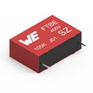 | SPECWCAP-FTBE Film Capacitors, –, – | Availability – | Status Activei| Production is active. Expected lifetime: >10 years. | Product seriesWCAP-FTBE Film Capacitors | – | – | – | – | – | – | Capacitance100 nF | Rated Voltage630 V (AC) | Rated Voltage 2504 V (DC) | – | Rate of Voltage Rise28 V/µs | Dissipation Factor1 % | Insulation Resistance9 GΩ | Pitch15 mm | Length18 mm | Width6 mm | Height12 mm | PackagingCarton | Capacitance±10% | SizePitch 15 mm | Operating Temperature -40 °C up to +85 °C | – | – | – | – | – | – | – | – | – | – | – | – | – | – | – | – | – | – | –Check availability | ||||||||||||||||||||||||||||||||||||||||||||||||||||||||||||||||||||||||||||||||||||||||||||||||||||||||||||||||||||||||||||||||||||||||||||||||||||||||||||||||||||||||||||||||||||||||||||||||||||||||||||||||||||||||||||||||||||||||||||||||||||||||||||||||||||||||||||||||||||||||||||||||||||||||||||||||||||||||||||||||||||||||||||||||||||||||||||||||||||||||||||||||||||||||||||||||||||||||||||||||||||||||||||||||||||||||||||||||||||||||||||||||||||||||||||||||||||||||||||||||||||||||||||||||||||||||||||||||||||||||||||||||||||||||||||||||||||||||||||||||||||||||||||||||||||||||||||||||||||||||||||||||||||||||||||||||||||||||||||||||||||||||||||||||||||||||||||||||||||||||||||||||||||||||||||||||||||||||||||||||||||||||||||||||||||||||||||||||||||||||||||||||||||||||||||||||||||||||||||||||||||||||||||||||||||||||||||||||||||||||||||||||||||||||||||||||||||||||||||||||||||||||||||||||||||||||||||||||||||||||||||||||||||||||||||||||||||||||||
| Expected Availability | Opening inventory | Quantity |
|---|---|---|
| Current Availability | – | – |