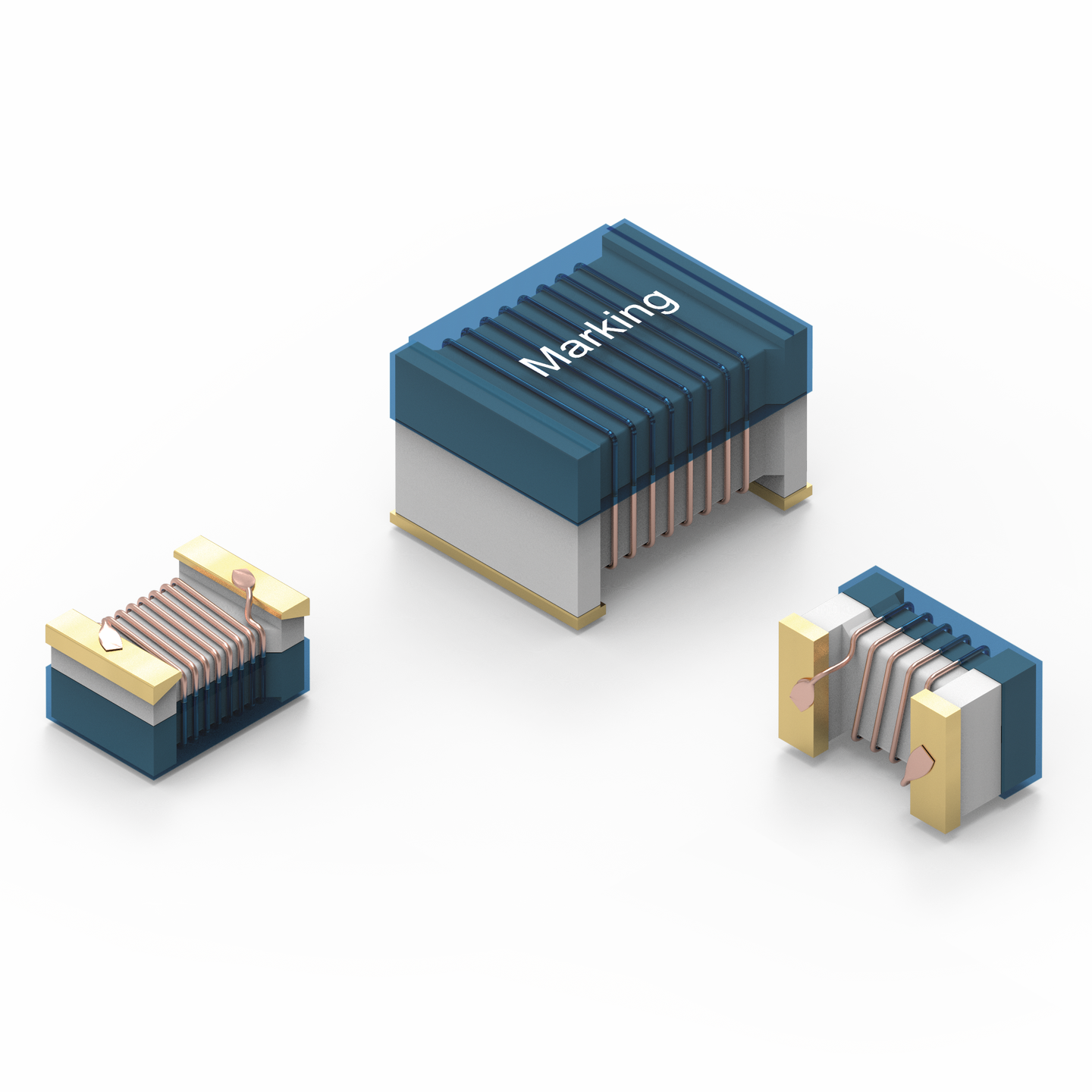
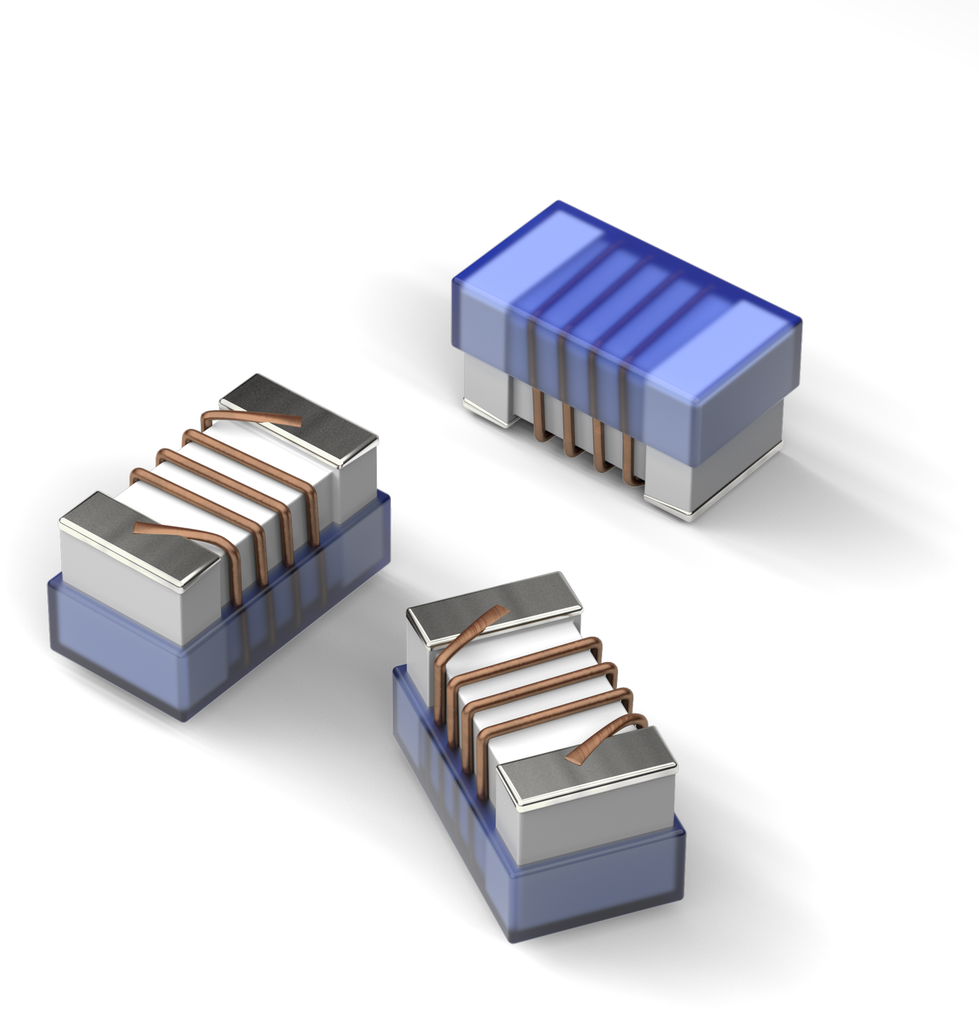
| Size | Dimensions | L (mm) | W (mm) | H (mm) | Mount | |
|---|---|---|---|---|---|---|
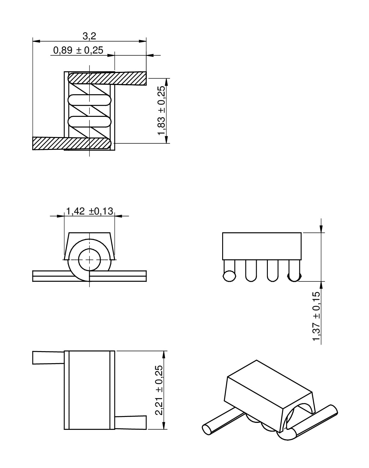
| 1322 | 2.21 | 1.42 | 1.37 | SMT | ||
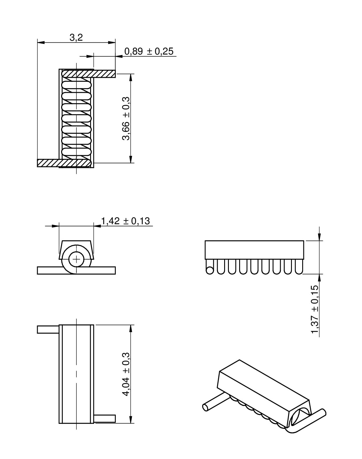
| 1340 | 4.04 | 1.42 | 1.37 | SMT | ||
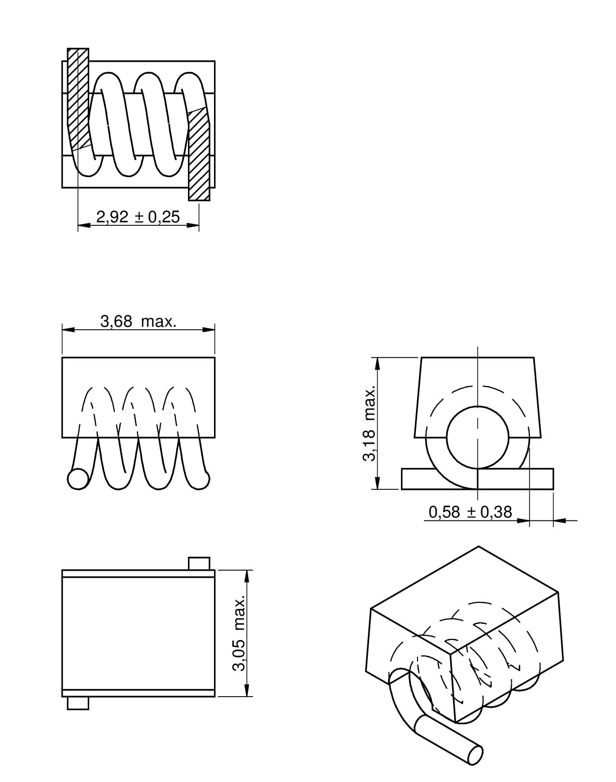
| 3136 | 3.68 | 3.05 | 3.18 | SMT | ||
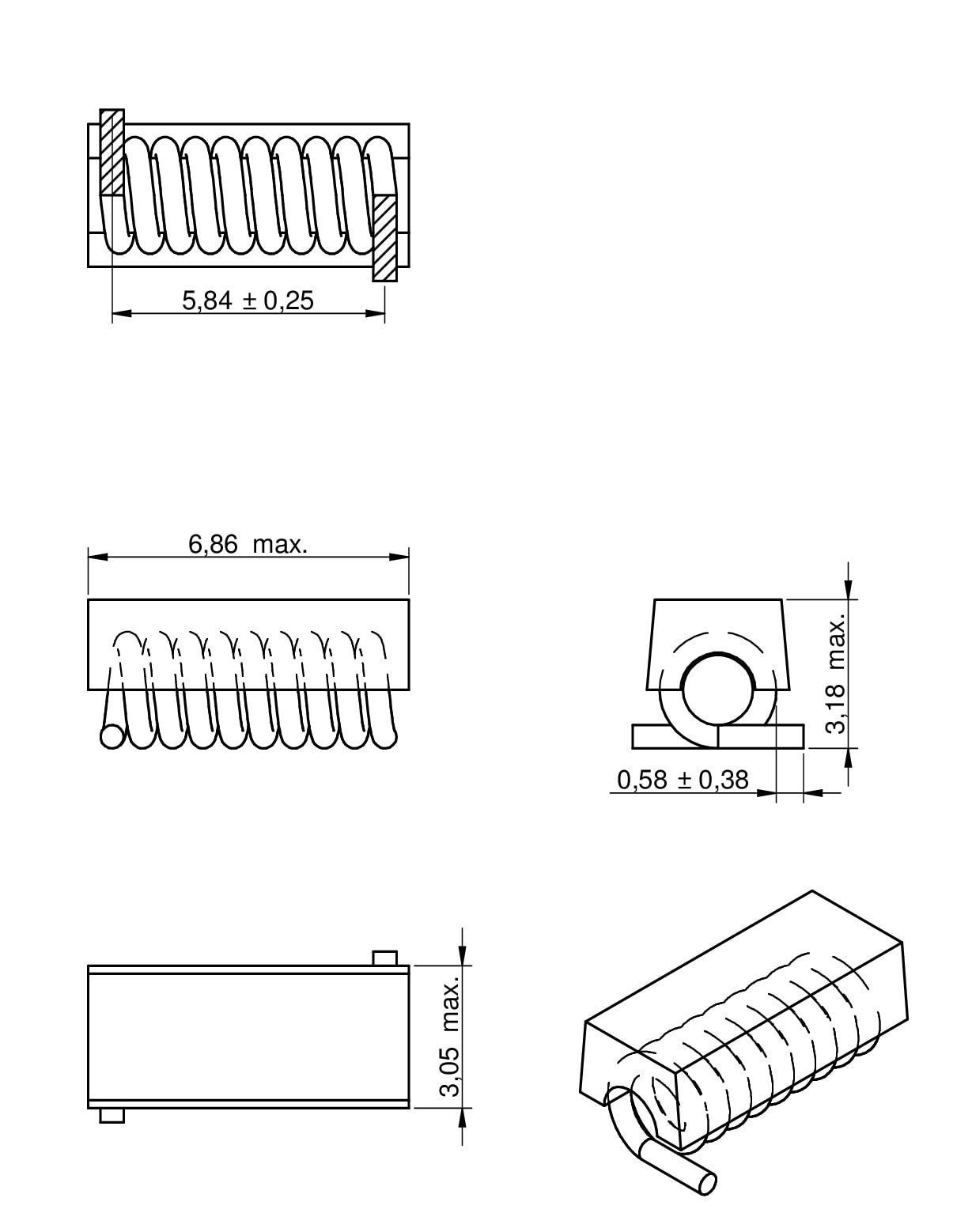
| 3168 | 6.68 | 3.05 | 3.18 | SMT | ||
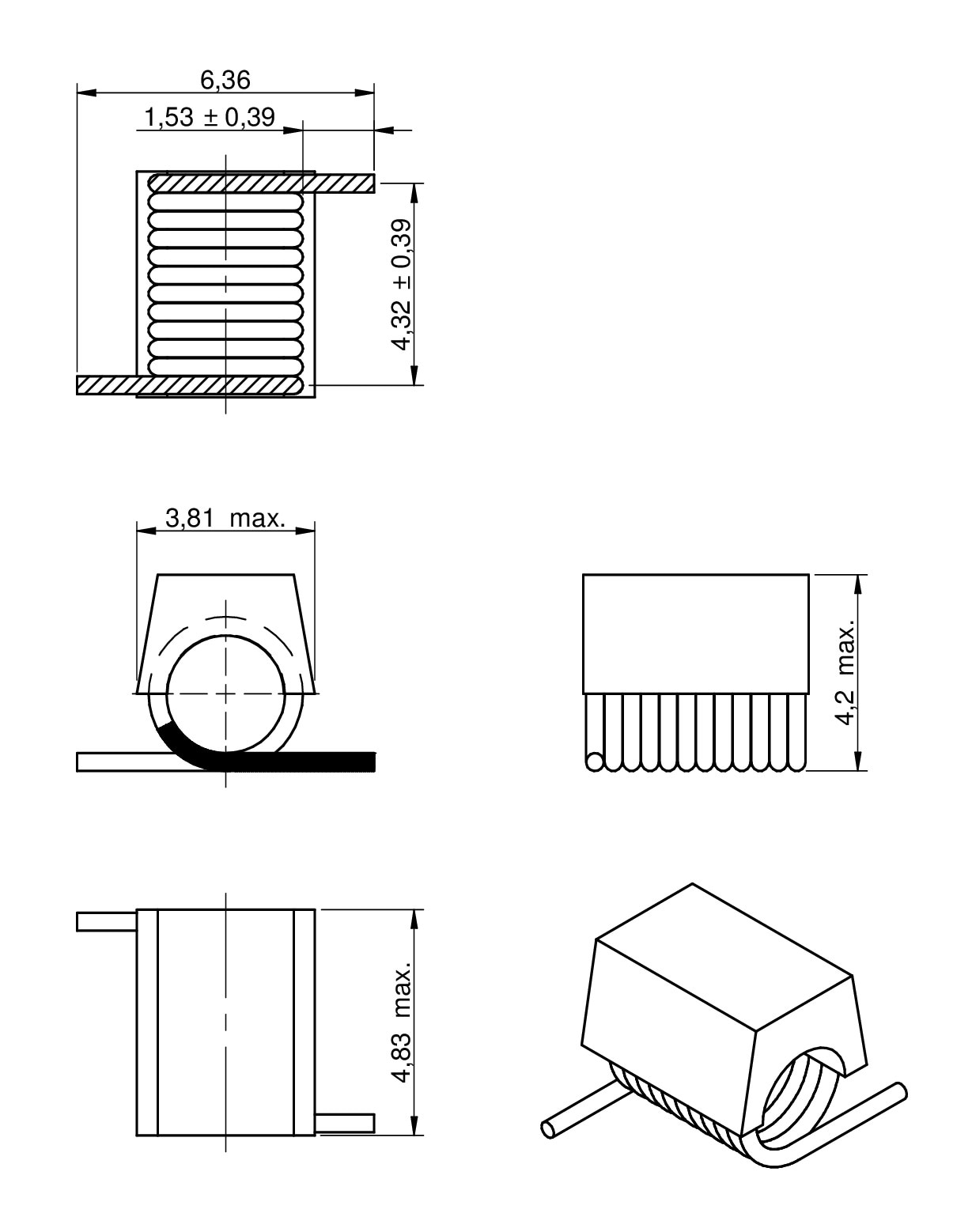
| 4248 | 4.83 | 3.81 | 4.2 | SMT | ||
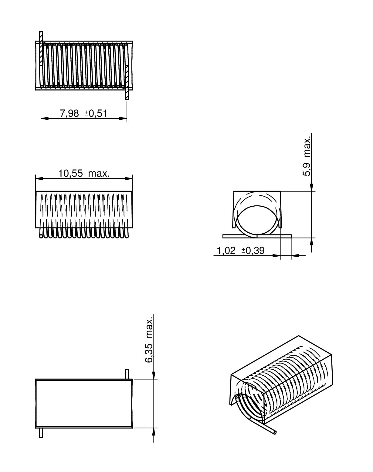
| 5910 | 10.55 | 6.35 | 5.9 | SMT |
LTSpice files
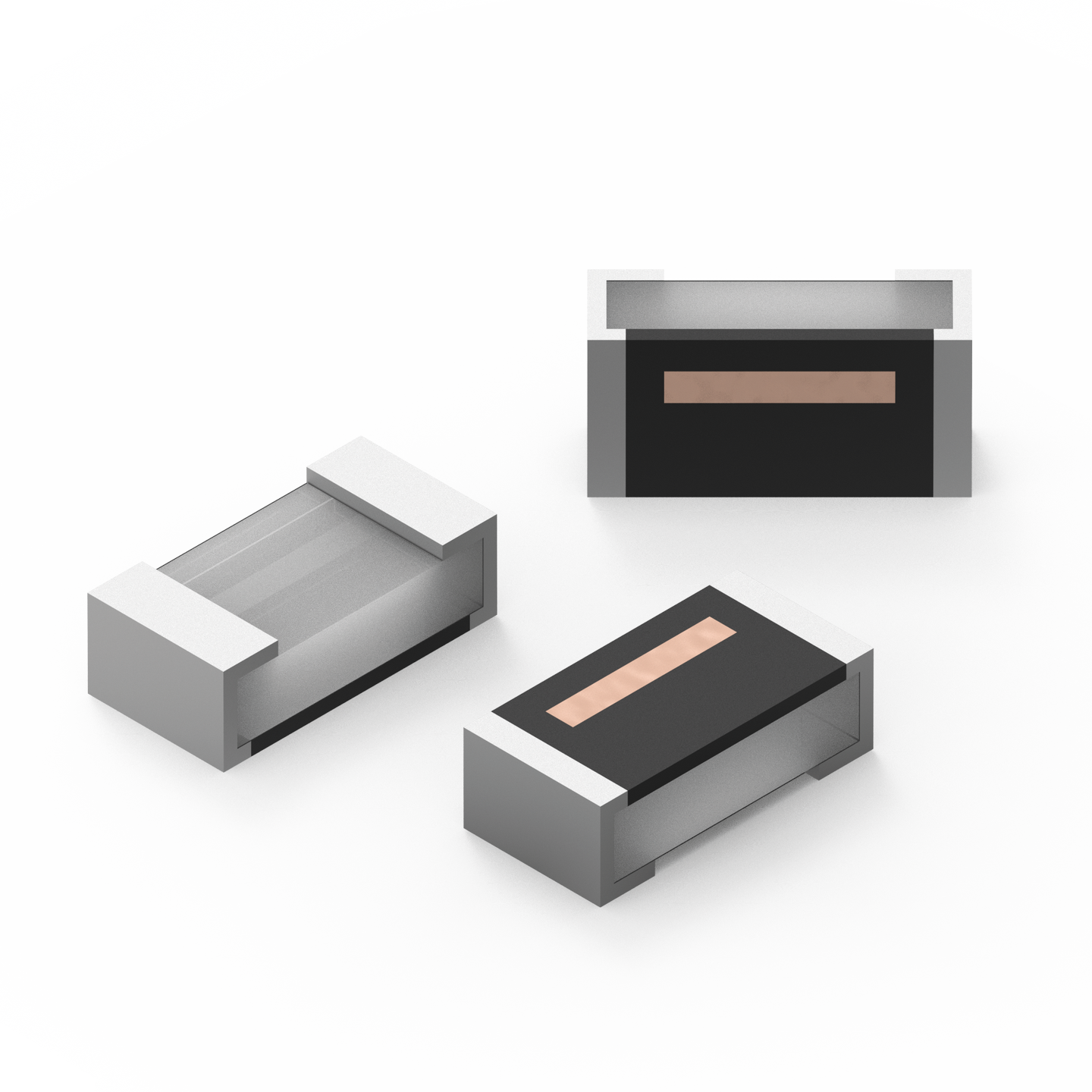
Characteristics
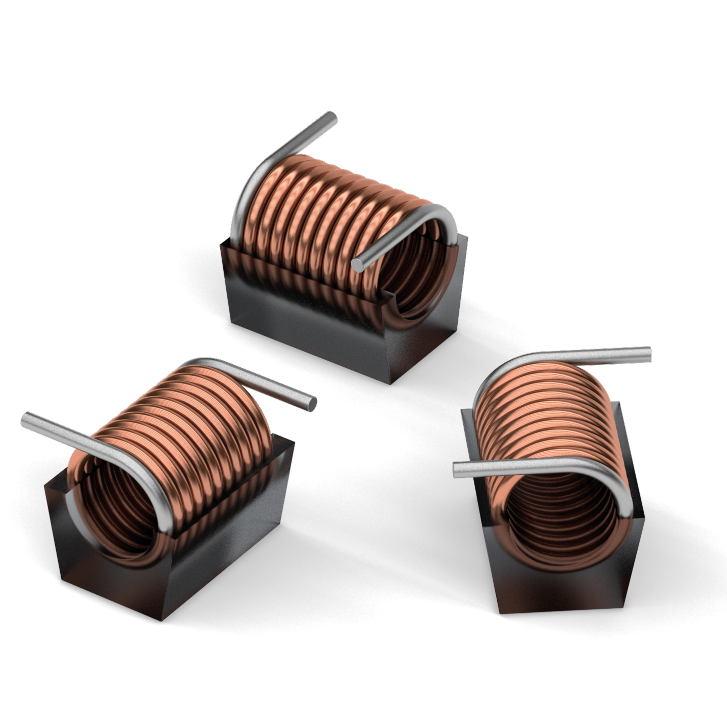
- Inductance values from 1.65 nH up to 538 nH
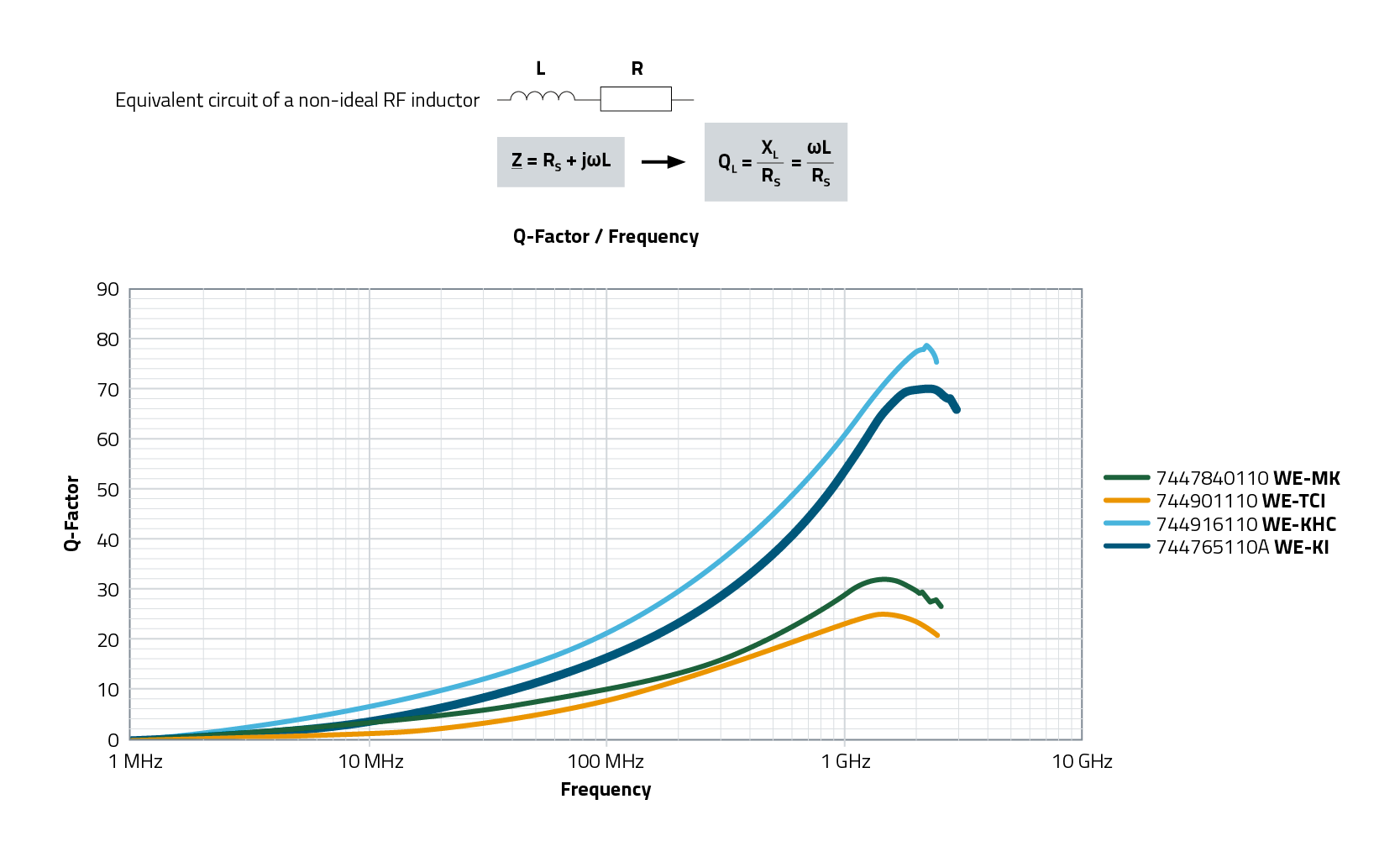
- Very high quality factor >100
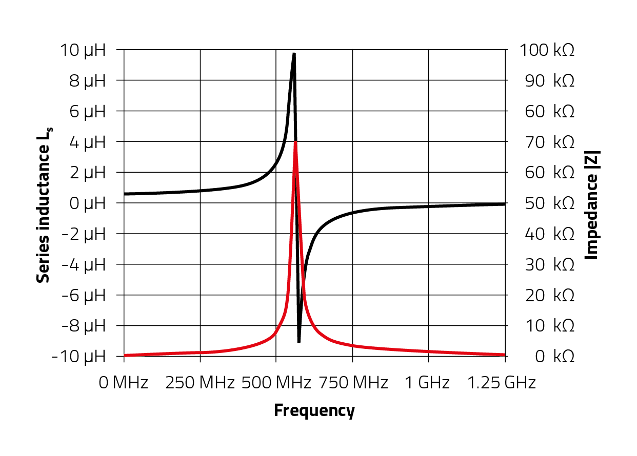
- High self-resonant frequency
- High currents up to 4.0 A
- Inductance tolerances 2%, 5 % and 10 %
- Pick and place process possible
- Good solderability (tinned connector pins)
- Operating temperature: -40 °C to +125 °C
Applications
- Especially for RF applications
- Ideal for high current applications
- Broad band filter
- RF-Decoupling
Application Notes
Products
All
1322
1340
3136
3168
4248
5910
| Order Code | Datasheet | Simulation | Downloads | Status | L (nH) | Tol. L | Test Condition L | Qmin. (%) | Test Condition Q | RDC max. (mΩ) | IR (A) | fres (GHz) | Design Kit | Samples |
|---|---|---|---|---|---|---|---|---|---|---|---|---|---|---|
| 744910016 | SPEC | 11 files | Active i| Production is active. Expected lifetime: >10 years. | 1.65 | ±10% | 800 MHz | 100 | 800 MHz | 4 | 1.6 | 10 | 74491 | ||
| 744913025 | SPEC | 10 files | Active i| Production is active. Expected lifetime: >10 years. | 2.5 | ±5% | 150 MHz | 140 | 150 MHz | 1.1 | 4 | 12.5 | 74491 | ||
| 744910025 | SPEC | 11 files | Active i| Production is active. Expected lifetime: >10 years. | 2.55 | ±5% | 800 MHz | 100 | 800 MHz | 5 | 1.6 | 8.2 | 74491 | ||
| 744910038 | SPEC | 11 files | Active i| Production is active. Expected lifetime: >10 years. | 3.85 | ±5% | 800 MHz | 100 | 800 MHz | 6 | 1.6 | 7.5 | 74491 | ||
| 744913050 | SPEC | 10 files | Active i| Production is active. Expected lifetime: >10 years. | 5 | ±5% | 150 MHz | 140 | 150 MHz | 1.8 | 4 | 6.5 | 74491 | ||
| 744913050G | SPEC | 10 files | Active i| Production is active. Expected lifetime: >10 years. | 5 | ±2% | 150 MHz | 140 | 150 MHz | 1.8 | 4 | 6.5 | – | ||
| 744910054 | SPEC | 11 files | Active i| Production is active. Expected lifetime: >10 years. | 5.45 | ±5% | 800 MHz | 100 | 800 MHz | 8 | 1.6 | 7 | 74491 | ||
| 744911056 | SPEC | 11 files | Active i| Production is active. Expected lifetime: >10 years. | 5.6 | ±5% | 800 MHz | 100 | 800 MHz | 9 | 1.6 | 6.5 | 74491 | ||
| 744911071 | SPEC | 11 files | Active i| Production is active. Expected lifetime: >10 years. | 7.15 | ±5% | 800 MHz | 100 | 800 MHz | 10 | 1.6 | 6 | 74491 | ||
| 744913080 | SPEC | 10 files | Active i| Production is active. Expected lifetime: >10 years. | 8 | ±5% | 150 MHz | 140 | 150 MHz | 2.6 | 4 | 5 | 74491 | ||
| 744913080G | SPEC | 10 files | Active i| Production is active. Expected lifetime: >10 years. | 8 | ±2% | 150 MHz | 140 | 150 MHz | 2.6 | 4 | 5 | – | ||
| 744911088 | SPEC | 11 files | Active i| Production is active. Expected lifetime: >10 years. | 8.8 | ±5% | 800 MHz | 100 | 800 MHz | 12 | 1.6 | 6 | 74491 | ||
| 744911098 | SPEC | 11 files | Active i| Production is active. Expected lifetime: >10 years. | 9.85 | ±5% | 800 MHz | 100 | 800 MHz | 13 | 1.6 | 5.2 | – | ||
| 744913112 | SPEC | 10 files | Active i| Production is active. Expected lifetime: >10 years. | 12.5 | ±5% | 150 MHz | 137 | 150 MHz | 3.4 | 4 | 3.3 | 74491 | ||
| 744913112G | SPEC | 10 files | Active i| Production is active. Expected lifetime: >10 years. | 12.5 | ±2% | 150 MHz | 137 | 150 MHz | 3.4 | 4 | 3.3 | – | ||
| 744911112 | SPEC | 11 files | Active i| Production is active. Expected lifetime: >10 years. | 12.55 | ±5% | 800 MHz | 100 | 800 MHz | 14 | 1.6 | 4.6 | 74491 | ||
| 744914117 | SPEC | 11 files | Active i| Production is active. Expected lifetime: >10 years. | 17.5 | ±5% | 150 MHz | 100 | 150 MHz | 4.5 | 4 | 2.2 | 74491 | ||
| 744914117G | SPEC | 11 files | Active i| Production is active. Expected lifetime: >10 years. | 17.5 | ±2% | 150 MHz | 100 | 150 MHz | 4.5 | 4 | 2.2 | – | ||
| 744913118 | SPEC | 10 files | Active i| Production is active. Expected lifetime: >10 years. | 18.5 | ±5% | 150 MHz | 132 | 150 MHz | 3.9 | 4 | 2.5 | 74491 | ||
| 744913118G | SPEC | 10 files | Active i| Production is active. Expected lifetime: >10 years. | 18.5 | ±2% | 150 MHz | 132 | 150 MHz | 3.9 | 4 | 2.5 | – | ||
| 744912122 | SPEC | 11 files | Active i| Production is active. Expected lifetime: >10 years. | 22 | ±5% | 150 MHz | 100 | 150 MHz | 4.2 | 3 | 3.2 | 74491 | ||
| 744914122 | SPEC | 11 files | Active i| Production is active. Expected lifetime: >10 years. | 22 | ±5% | 150 MHz | 102 | 150 MHz | 5.2 | 4 | 2.1 | 74491 | ||
| 744912122G | SPEC | 11 files | Active i| Production is active. Expected lifetime: >10 years. | 22 | ±2% | 150 MHz | 100 | 150 MHz | 4.2 | 3 | 3.2 | – | ||
| 744914122G | SPEC | 11 files | Active i| Production is active. Expected lifetime: >10 years. | 22 | ±2% | 150 MHz | 102 | 150 MHz | 5.2 | 4 | 2.1 | – | ||
| 744912127 | SPEC | 11 files | Active i| Production is active. Expected lifetime: >10 years. | 27 | ±5% | 150 MHz | 100 | 150 MHz | 4 | 3.5 | 2.7 | 74491 | ||
| 744912127G | SPEC | 11 files | Active i| Production is active. Expected lifetime: >10 years. | 27 | ±2% | 150 MHz | 100 | 150 MHz | 4 | 3.5 | 2.7 | – | ||
| 744914128 | SPEC | 11 files | Active i| Production is active. Expected lifetime: >10 years. | 28 | ±5% | 150 MHz | 105 | 150 MHz | 6 | 4 | 1.8 | 74491 | ||
| 744914128G | SPEC | 11 files | Active i| Production is active. Expected lifetime: >10 years. | 28 | ±2% | 150 MHz | 105 | 150 MHz | 6 | 4 | 1.8 | – | ||
| 744912133 | SPEC | 11 files | Active i| Production is active. Expected lifetime: >10 years. | 33 | ±5% | 150 MHz | 100 | 150 MHz | 4.8 | 3 | 2.5 | 74491 | ||
| 744912133G | SPEC | 11 files | Active i| Production is active. Expected lifetime: >10 years. | 33 | ±2% | 150 MHz | 100 | 150 MHz | 4.8 | 3 | 2.5 | – | ||
| 744914135 | SPEC | 11 files | Active i| Production is active. Expected lifetime: >10 years. | 35.5 | ±5% | 150 MHz | 112 | 150 MHz | 6.8 | 4 | 1.5 | 74491 | ||
| 744914135G | SPEC | 11 files | Active i| Production is active. Expected lifetime: >10 years. | 35.5 | ±2% | 150 MHz | 112 | 150 MHz | 6.8 | 4 | 1.5 | – | ||
| 744912139 | SPEC | 11 files | Active i| Production is active. Expected lifetime: >10 years. | 39 | ±5% | 150 MHz | 100 | 150 MHz | 4.4 | 3 | 2.1 | 74491 | ||
| 744912139G | SPEC | 11 files | Active i| Production is active. Expected lifetime: >10 years. | 39 | ±2% | 150 MHz | 100 | 150 MHz | 4.4 | 3 | 2.1 | – | ||
| 744914143 | SPEC | 11 files | Active i| Production is active. Expected lifetime: >10 years. | 43 | ±5% | 150 MHz | 106 | 150 MHz | 7.9 | 4 | 1.2 | 74491 | ||
| 744914143G | SPEC | 11 files | Active i| Production is active. Expected lifetime: >10 years. | 43 | ±2% | 150 MHz | 106 | 150 MHz | 7.9 | 4 | 1.2 | – | ||
| 744912147 | SPEC | 11 files | Active i| Production is active. Expected lifetime: >10 years. | 47 | ±5% | 150 MHz | 100 | 150 MHz | 5.6 | 3 | 2.1 | 74491 | ||
| 744912147G | SPEC | 11 files | Active i| Production is active. Expected lifetime: >10 years. | 47 | ±2% | 150 MHz | 100 | 150 MHz | 5.6 | 3 | 2.1 | – | ||
| 744912156 | SPEC | 11 files | Active i| Production is active. Expected lifetime: >10 years. | 56 | ±5% | 150 MHz | 100 | 150 MHz | 6.2 | 3 | 1.5 | 74491 | ||
| 744912156G | SPEC | 11 files | Active i| Production is active. Expected lifetime: >10 years. | 56 | ±2% | 150 MHz | 100 | 150 MHz | 6.2 | 3 | 1.5 | – | ||
| 744912168 | SPEC | 11 files | Active i| Production is active. Expected lifetime: >10 years. | 68 | ±5% | 150 MHz | 100 | 150 MHz | 8.2 | 2.5 | 1.5 | 74491 | ||
| 744912168G | SPEC | 11 files | Active i| Production is active. Expected lifetime: >10 years. | 68 | ±2% | 150 MHz | 100 | 150 MHz | 8.2 | 2.5 | 1.5 | – | ||
| 744912182 | SPEC | 11 files | Active i| Production is active. Expected lifetime: >10 years. | 82 | ±5% | 150 MHz | 100 | 150 MHz | 9.4 | 2.5 | 1.3 | 74491 | ||
| 744912182G | SPEC | 11 files | Active i| Production is active. Expected lifetime: >10 years. | 82 | ±2% | 150 MHz | 100 | 150 MHz | 9.4 | 2.5 | 1.3 | – | ||
| 744918190 | SPEC | 11 files | Active i| Production is active. Expected lifetime: >10 years. | 90 | ±5% | 50 MHz | 100 | 50 MHz | 15 | 3.5 | 1.14 | – | ||
| 744912210 | SPEC | 11 files | Active i| Production is active. Expected lifetime: >10 years. | 100 | ±5% | 150 MHz | 100 | 150 MHz | 12.3 | 1.7 | 1.2 | 74491 | ||
| 744912210G | SPEC | 11 files | Active i| Production is active. Expected lifetime: >10 years. | 100 | ±2% | 150 MHz | 100 | 150 MHz | 12.3 | 1.7 | 1.2 | – | ||
| 744918211 | SPEC | 11 files | Active i| Production is active. Expected lifetime: >10 years. | 111 | ±5% | 50 MHz | 100 | 50 MHz | 15 | 3.5 | 1.02 | – | ||
| 744912212 | SPEC | 11 files | Active i| Production is active. Expected lifetime: >10 years. | 120 | ±5% | 150 MHz | 100 | 150 MHz | 17.3 | 1.5 | 1.1 | 74491 | ||
| 744912212G | SPEC | 11 files | Active i| Production is active. Expected lifetime: >10 years. | 120 | ±2% | 150 MHz | 100 | 150 MHz | 17.3 | 1.5 | 1.1 | – | ||
| 744918213 | SPEC | 11 files | Active i| Production is active. Expected lifetime: >10 years. | 130 | ±5% | 50 MHz | 100 | 50 MHz | 20 | 3 | 0.9 | – | ||
| 744918217 | SPEC | 11 files | Active i| Production is active. Expected lifetime: >10 years. | 169 | ±5% | 50 MHz | 100 | 50 MHz | 25 | 3 | 0.875 | – | ||
| 744918220 | SPEC | 11 files | Active i| Production is active. Expected lifetime: >10 years. | 206 | ±5% | 50 MHz | 100 | 50 MHz | 30 | 3 | 0.8 | – | ||
| 744918222 | SPEC | 11 files | Active i| Production is active. Expected lifetime: >10 years. | 222 | ±5% | 50 MHz | 100 | 50 MHz | 35 | 3 | 0.73 | – | ||
| 744918224 | SPEC | 11 files | Active i| Production is active. Expected lifetime: >10 years. | 246 | ±5% | 50 MHz | 100 | 50 MHz | 35 | 3 | 0.685 | – | ||
| 744918230 | SPEC | 11 files | Active i| Production is active. Expected lifetime: >10 years. | 307 | ±5% | 50 MHz | 100 | 50 MHz | 35 | 3 | 0.66 | – | ||
| 744918238 | SPEC | 11 files | Active i| Production is active. Expected lifetime: >10 years. | 380 | ±5% | 50 MHz | 100 | 50 MHz | 50 | 2.5 | 0.59 | – | ||
| 744918242 | SPEC | 11 files | Active i| Production is active. Expected lifetime: >10 years. | 422 | ±5% | 50 MHz | 100 | 50 MHz | 60 | 2.5 | 0.54 | – | ||
| 744918249 | SPEC | 11 files | Active i| Production is active. Expected lifetime: >10 years. | 491 | ±5% | 50 MHz | 100 | 50 MHz | 65 | 2 | 0.535 | – | ||
| 744918254 | SPEC | 11 files | Active i| Production is active. Expected lifetime: >10 years. | 538 | ±5% | 50 MHz | 100 | 50 MHz | 90 | 2 | 0.49 | – |
| Order Code | Datasheet | Simulation |
|---|---|---|
| 744910016 | SPEC | |
| 744913025 | SPEC | |
| 744910025 | SPEC | |
| 744910038 | SPEC | |
| 744913050 | SPEC | |
| 744913050G | SPEC | |
| 744910054 | SPEC | |
| 744911056 | SPEC | |
| 744911071 | SPEC | |
| 744913080 | SPEC | |
| 744913080G | SPEC | |
| 744911088 | SPEC | |
| 744911098 | SPEC | |
| 744913112 | SPEC | |
| 744913112G | SPEC | |
| 744911112 | SPEC | |
| 744914117 | SPEC | |
| 744914117G | SPEC | |
| 744913118 | SPEC | |
| 744913118G | SPEC | |
| 744912122 | SPEC | |
| 744914122 | SPEC | |
| 744912122G | SPEC | |
| 744914122G | SPEC | |
| 744912127 | SPEC | |
| 744912127G | SPEC | |
| 744914128 | SPEC | |
| 744914128G | SPEC | |
| 744912133 | SPEC | |
| 744912133G | SPEC | |
| 744914135 | SPEC | |
| 744914135G | SPEC | |
| 744912139 | SPEC | |
| 744912139G | SPEC | |
| 744914143 | SPEC | |
| 744914143G | SPEC | |
| 744912147 | SPEC | |
| 744912147G | SPEC | |
| 744912156 | SPEC | |
| 744912156G | SPEC | |
| 744912168 | SPEC | |
| 744912168G | SPEC | |
| 744912182 | SPEC | |
| 744912182G | SPEC | |
| 744918190 | SPEC | |
| 744912210 | SPEC | |
| 744912210G | SPEC | |
| 744918211 | SPEC | |
| 744912212 | SPEC | |
| 744912212G | SPEC | |
| 744918213 | SPEC | |
| 744918217 | SPEC | |
| 744918220 | SPEC | |
| 744918222 | SPEC | |
| 744918224 | SPEC | |
| 744918230 | SPEC | |
| 744918238 | SPEC | |
| 744918242 | SPEC | |
| 744918249 | SPEC | |
| 744918254 | SPEC |
| Samples |
|---|
| Order Code | Datasheet | Simulation | Downloads | Status | L (nH) | Tol. L | Test Condition L | Qmin. (%) | Test Condition Q | RDC max. (mΩ) | IR (A) | fres (GHz) | Design Kit | Samples |
|---|


Assortments
Articles from this product series can be found in the following assortments: