OverviewAll product unitsProduct unitPassive ComponentsProduct groupCapacitorsProduct familyAluminum Polymer CapacitorsMounting StyleH-Chip SMTProduct seriesWCAP-PHLE Aluminum Polymer Capacitors

WCAP-PHLE Aluminum Polymer Capacitors

Low ESR

WCAP-PHLE Aluminum Polymer Capacitors

Characteristics

  • Low ESR product series
  • High ripple current capability
  • Low profile
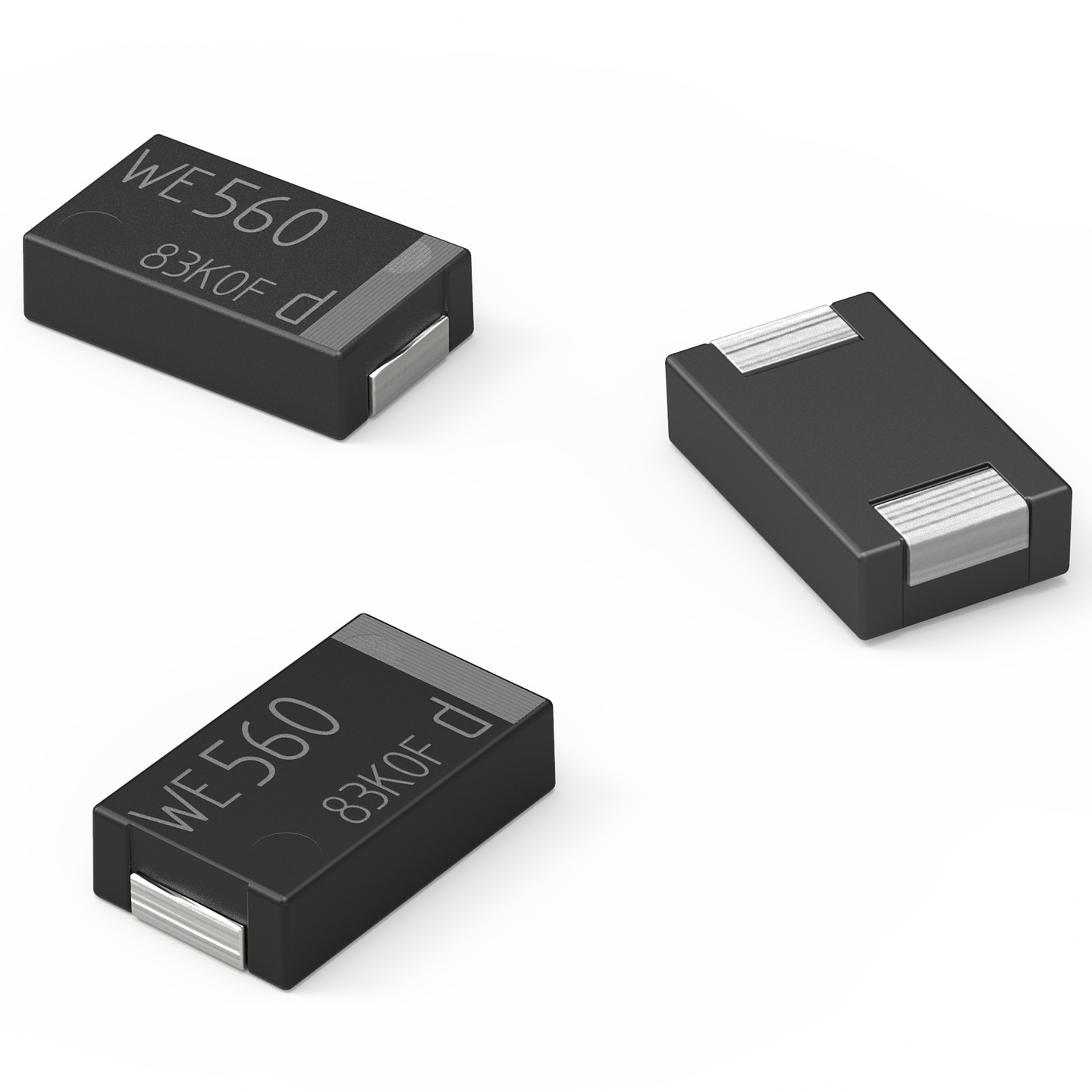
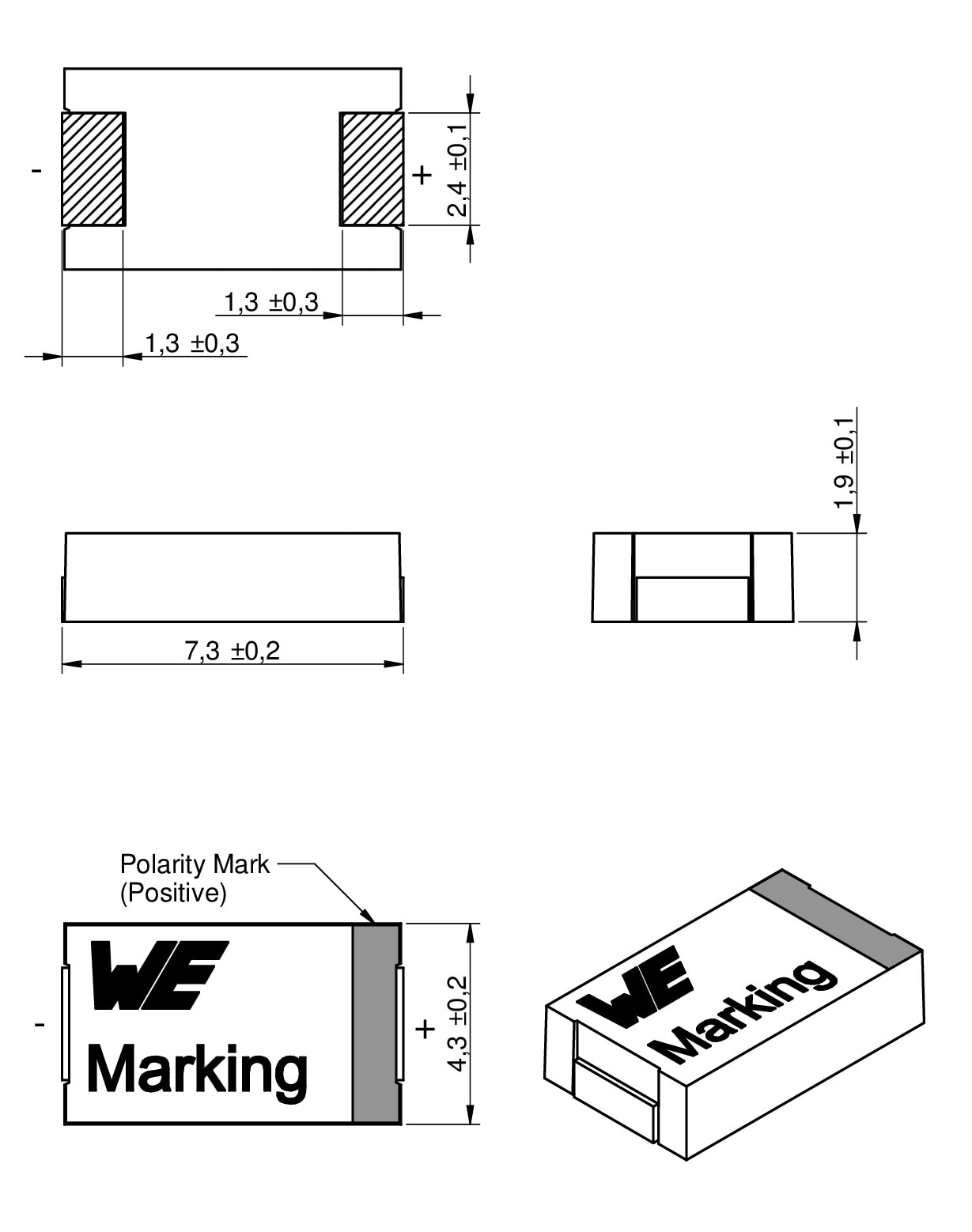
  • Mounting style: H-Chip SMT
  • Recommended soldering: Reflow soldering

Applications

  • Noise suppression
  • Input and output capacitor for DC/DC converter
  • e.g. USB charger, smart meter, power bank, server, SSD

Products

Order Code Data­sheet Simu­lation Downloads StatusCVR
(V (DC))
Endurance
(h)
Operating TemperatureIRIPPLE
(mA)
RESR
(mΩ)
ILeak
(µA)
DF
(%)
L
(mm)
W
(mm)
H
(mm)
Packaging Samples
875035019001SPEC
9 files Active i| Production is active. Expected lifetime: >10 years.100 µF 4 2000 -55 °C up to +105 °C 6300 9 40 6 7.3 4.3 1.9 13" Tape & Reel
875035019002SPEC
9 files Active i| Production is active. Expected lifetime: >10 years.180 µF 4 2000 -55 °C up to +105 °C 6300 9 72 6 7.3 4.3 1.9 13" Tape & Reel
875035119002SPEC
9 files Active i| Production is active. Expected lifetime: >10 years.180 µF 6.3 2000 -55 °C up to +105 °C 6300 9 113.4 6 7.3 4.3 1.9 13" Tape & Reel
875035019003SPEC
9 files Active i| Production is active. Expected lifetime: >10 years.220 µF 4 2000 -55 °C up to +105 °C 6300 9 88 6 7.3 4.3 1.9 13" Tape & Reel
875036219012SPEC
9 files Active i| Production is active. Expected lifetime: >10 years.330 µF 2 2000 -55 °C up to +105 °C 8500 4.5 66 6 7.3 4.3 1.9 13" Tape & Reel
875036319012SPEC
9 files Active i| Production is active. Expected lifetime: >10 years.330 µF 2.5 2000 -55 °C up to +105 °C 8500 4.5 82.5 6 7.3 4.3 1.9 13" Tape & Reel
875036219015SPEC
9 files Active i| Production is active. Expected lifetime: >10 years.390 µF 2 2000 -55 °C up to +105 °C 8500 4.5 78 6 7.3 4.3 1.9 13" Tape & Reel
875036319015SPEC
9 files Active i| Production is active. Expected lifetime: >10 years.390 µF 2.5 2000 -55 °C up to +105 °C 8500 4.5 97.5 6 7.3 4.3 1.9 13" Tape & Reel
875036219018SPEC
9 files Active i| Production is active. Expected lifetime: >10 years.470 µF 2 2000 -55 °C up to +105 °C 8500 4.5 94 6 7.3 4.3 1.9 13" Tape & Reel
875036319018SPEC
9 files Active i| Production is active. Expected lifetime: >10 years.470 µF 2.5 2000 -55 °C up to +105 °C 8500 4.5 117.5 6 7.3 4.3 1.9 13" Tape & Reel
875036219019SPEC
9 files Active i| Production is active. Expected lifetime: >10 years.560 µF 2 2000 -55 °C up to +105 °C 8500 4.5 112 6 7.3 4.3 1.9 13" Tape & Reel
Order Code Data­sheet Simu­lation
875035019001SPEC
875035019002SPEC
875035119002SPEC
875035019003SPEC
875036219012SPEC
875036319012SPEC
875036219015SPEC
875036319015SPEC
875036219018SPEC
875036319018SPEC
875036219019SPEC
Samples
Order Code Data­sheet Simu­lation Downloads StatusCVR
(V (DC))
Endurance
(h)
Operating TemperatureIRIPPLE
(mA)
RESR
(mΩ)
ILeak
(µA)
DF
(%)
L
(mm)
W
(mm)
H
(mm)
Packaging Samples

Würth Elektronik capacitors

Big portfolio available ex stock

Würth Elektronik capacitors

Big portfolio available ex stock

Würth Elektronik has extended its capacitor portfolio. You will find an overview of our current technologies available ex stock in the graph. More details (e.g. series, characteristics, features, applications, etc.) about each product family can be found in the flyer or for example below. In our flyer you will also find information about our services.

Relationship between voltage and capacitance in the diagram

Available series

  • Series WCAP-PTXX

    • Mounting Style: Radial THT
    • Series: PTG5, PTHR, PTHT, PT5H
    • Capacitance: 10 – 2000 µF
    • Voltage: 6.3 – 100 V (DC)
  • Series WCAP-PSXX

    • Mounting Style: V-Chip SMT
    • Series: PSLC, PSLP, PSHP
    • Capacitance: : 4.7 – 2000 µF
    • Voltage: 6.3 – 100 V (DC)
  • Series WCAP-PHXX

    • Mounting Style: H-Chip SMT
    • Series: PHGP, PHLE, PHSE
    • Capacitance: 100 – 560 µF
    • Voltage: 2 – 6.3 V (DC)

Comparison of aluminum capacitors

Aluminium-Elektrolytkondensatoren

Aluminum electrolytic capacitors

  • Stable capacitance values at high temperature
  • High voltage ratings
  • Low leakage current
Aluminium-Hybrid-Polymer-Kondensatoren

Aluminum hybrid polymer capacitors

  • Low ESR
  • High ripple current characteristics
  • High stability over the temperature range
  • Low leakage current
  • High lifetime performance
Aluminium-Polymer-Kondensatoren

Aluminum polymer capacitors

  • Low ESR
  • High ripple current characteristics
  • High lifetime performance

Construction

Drawing of a wound capacitor with labels for anode foil, cathode foil, separator paper (soaked with electrolyte), and terminals for anode and cathode.

Wound capacitor

Aluminum electrolytic capacitors are wound capacitors. These consist of aluminum foils with a layer of paper in between.

Cross-section of an aluminum polymer capacitor with anode, cathode, dielectric, separator paper, and conductive polymer.

Layer structure

The aluminum foil of the anode is formed by anodic oxidation before the winding process, so that the dielectric (oxide layer) is strengthened. The winding is impregnated with a monomer. The highly conductive polymer is formed by polymerisation. The paper interlayer ensures an even structure and a defined distance between the anode and cathode foil.

Example applications

Measurements

Redexpert

Measurements

Redexpert

With the help of REDEXPERT you will find the right capacitor based on your technical requirements. The tool supports, for example, with measured values for capacitance, impedance, ESR and dissipation factor (DF). The ability to compare individual components with each other in terms of measured values enables convenient component selection.

Computer screen with overlapping windows, graphs, and red 3D text: 'ONLINE PLATFORM BASED ON MEASURED VALUES.'

Lifetime

Lifetime calculator

With this tool you can calculate your maximum expected lifetime. Depending on the product family, a different formula is used for the calculation. This calculator can be found in the aluminum capacitor module on the REDEXPERT platform.

Icon of two parallel capacitors with a clock above, next to the text 'Lifetime Calculator.'

Expected lifetime vs. temperature

In this graph you can find the difference in expected lifetime between our different product families. The curves are based on the different formulas and the endurance of this product. The lifetime table and formula can be found in the information sheet.

Grafik, die das Verhältnis zwischen Temperatur und Lebensdauer von Kondensatoren zeigt.

Webinar

Introduction to the capacitor technologies and how to use them

Webinar

Introduction to the capacitor technologies and how to use them

Capacitors make up two thirds of all electronic components and there is a huge diversity of technologies which can overwhelm young engineers. All capacitors store electrical energy in the electrical field created in a dielectric material and they are used for very diverse applications like voltage stability and filtering. How that works differs between tiny MLCCs and huge electrolytic cells, from pF ratings up to the hundreds of Farads in supercapacitors. In this presentation, we introduce different capacitor solutions taking into account the advantages and disadvantages and with a focus on the final application.

alttext yt_img_for_code_YCVcrKE-6ok.jpg 1745304827

Application notes and documents

  • All Capacitors are "Audio Capacitors"

    There is an ongoing discussion within the audio engineering community about the sound quality of amplifiers concerning the audibility of signal distortions. Apparently, capacitors used for coupling and decoupling signals are suspected to be the source or at least a contributor to high-frequency distortions that influence the hearing impression.

  • Application Note ANP071: Aluminum Electrolytic vs. Aluminum Polymer Capacitor and how its benefits are used properly

    Aluminum polymer capacitor is a sub-form of the electrolytic capacitors. The special feature of these capacitor types is that a conductive polymer is used instead of a liquid electrolyte. This requires a special processing step, which is carried out during production. In this chemical reaction, the so-called polymerization, by heating, the still liquid monomer that has been impregnated in place of electrolyte in the separator paper is cross-linked to a solid polymer.

  • Support Note SN008: Expected Lifetime of Aluminum Electrolytic and Aluminum Polymer Capacitor

    The life cycle of a capacitor depends on many factors of the application. An important factor is the temperature or rather thermal load, as it is responsible for the fact that internal structures age over time and the electrical properties deteriorate. This results in increased leakage current, increasing the ESR, which in turn leads to a further increase of the temperature.

  • Support Note SN019: Afraid of aging? The effects of time on electrolytic capacitors

    Since the development and production of electrolytic capacitors, designers have had to deal with the issues of aging and shelf life of these products. Electrolytic capacitors have been around for a very long time, but the rapid increase did not occur until the 1960s. There are still many "myths" from that time that revolve around the aging and shelf life of these capacitors.

  • ANP125 Acoustic Effect of Harmonic Distortions caused by Aluminum Electrolytic Capacitors

    This note reports a comparative study of total harmonic distortions (THD) caused by commercial electrolytic capacitors, as produced by Würth Elektronik eiSos as well as purpose-built items. The discussion about the audibility of distortions is made on the basis of human sound perception. This note arrives at the conclusion that capacitors do not add significant distortions to fundamental frequencies as they transfer signals. Modifications of the electrolyte or separation paper have almost no effect on the THD.

FAQ aluminium capacitors

Datasheet WCAP-CSRF

For most parts you can find the detailed information about packaging in the datasheet: If you cannot find them, please get in contact with Würth Elektronik. E.g. you can use the chat on the website.

Example: Page 3 of WCAP-CSRF component datasheet.


You can find the certifications in the datasheet, page 2.

In the case of X/Y safety capacitors, certification information can be found in PDF format in the online platform REDEXPERT.

These links are shown at the right end of the table, under the column “Certificates”.


We provide the document with all the values on our homepage.

You can also download the document by searching for “FIT” or “MTBF” in our download center.

This document reveals the FIT (Failures in time) and MTBF (Mean time between failures) values that can be calculated for each series based on the electrical stress (voltage applied in the case of capacitors) and the temperature applied according to calculation models of Telcordia SR-332 Issue 3.

Please refer to the table of contents at the beginning of the document to find the values for capacitors.


  1. Würth Elektronik part number
  2. Actual ambient operating temperature which the capacitor is used at (°C)
  3. Operating ripple current flowing through the capacitor (A, RMS)
  4. Frequency of the ripple current (Hz)
  5. Operating voltage which is applied to the capacitor (V(DC))

Table shows the multiplier for ripple current vs frequency

Please find the following example (datasheet, page 2)

For all capacitors of series WCAP-A***, WCAP-P*** and WCAP-H*** there is a maximum ripple current in the datasheet. This ripple current is defined at a specific frequency and temperature and it is given as a RMS (root mean square) value.

Since the ripple current is defined at a certain frequency, it can be converted into the respective value for certain frequencies using factors. These factors can be found in the data sheet.

Let’s assume that the rated ripple current of this part (400V part) is 1 A @ 120 Hz. The max. ripple current @ max. temperature and 10 kHz is then 1.41 A.Furthermore, the ripple current can also be increased if the temperature is below the maximum component temperature. However, this must always be considered in the context of the expected lifetime.

The lifetime calculation in RedExpert can be used for a simple estimate. For detailed considerations, please use one of the many ways of contacting Würth Elektronik to obtain a specific lifetime estimate for your capacitor selection. This value may be increased or decreased if the operating conditions in the application are different from the datasheet.


Extract from the Lifetime calculator in Redexpert

You can find the lifetime calculation on REDEXPERT.

The lifetime calculator may be opened with the sand clock button in the left of the Electrolytic/Polymer/Hybrid . The user must be registered and logged, as this functionality is restricted to registered users.

You can set the conditions in the input box and for Frequency and Temperature you may also move the sliders in the graphs in the right.


Videos

The H-Chip Aluminum Polymer Capacitor from Würth Elektronik

Videos

#askLorandt explains: What miniaturization means for MLCCs and what alternatives are possible

Videos

#askLorandt explains: DC/DC Converter Voltage Ripple vs. ESR of Different Capacitor Technologies

Videos

How to choose the right capacitor type for a circuit?! || Film vs. Ceramic vs. Electrolytic

Videos

Webinar: Introduction to the capacitor technologies and how to use them