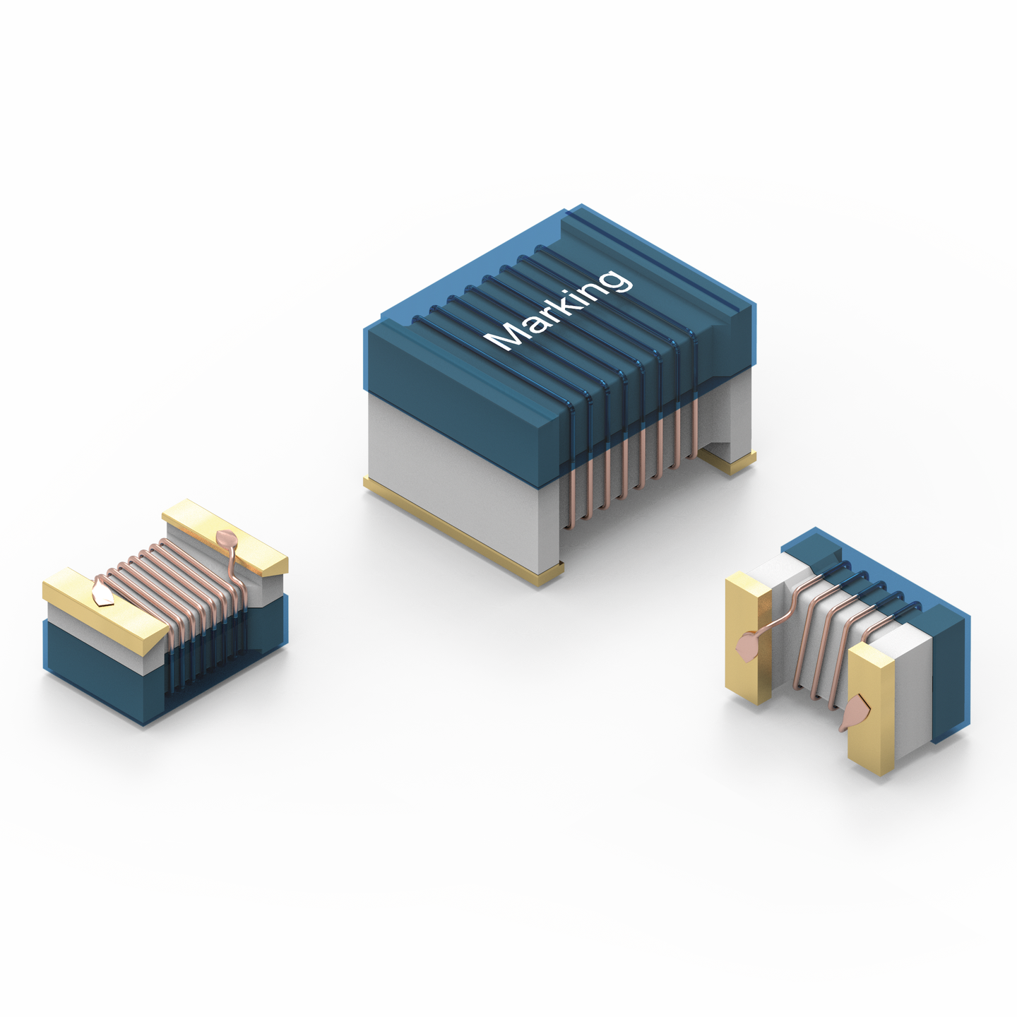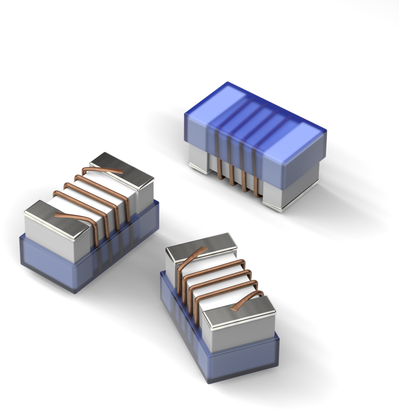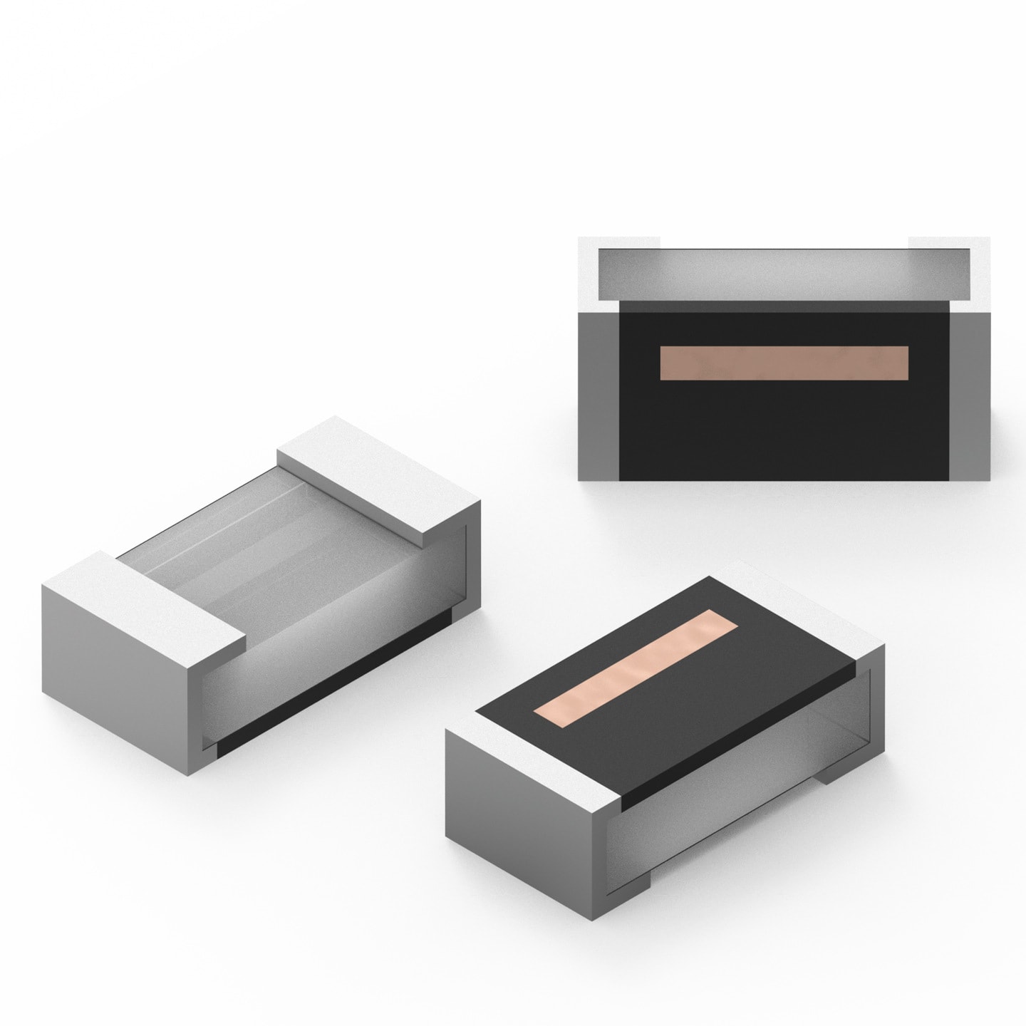
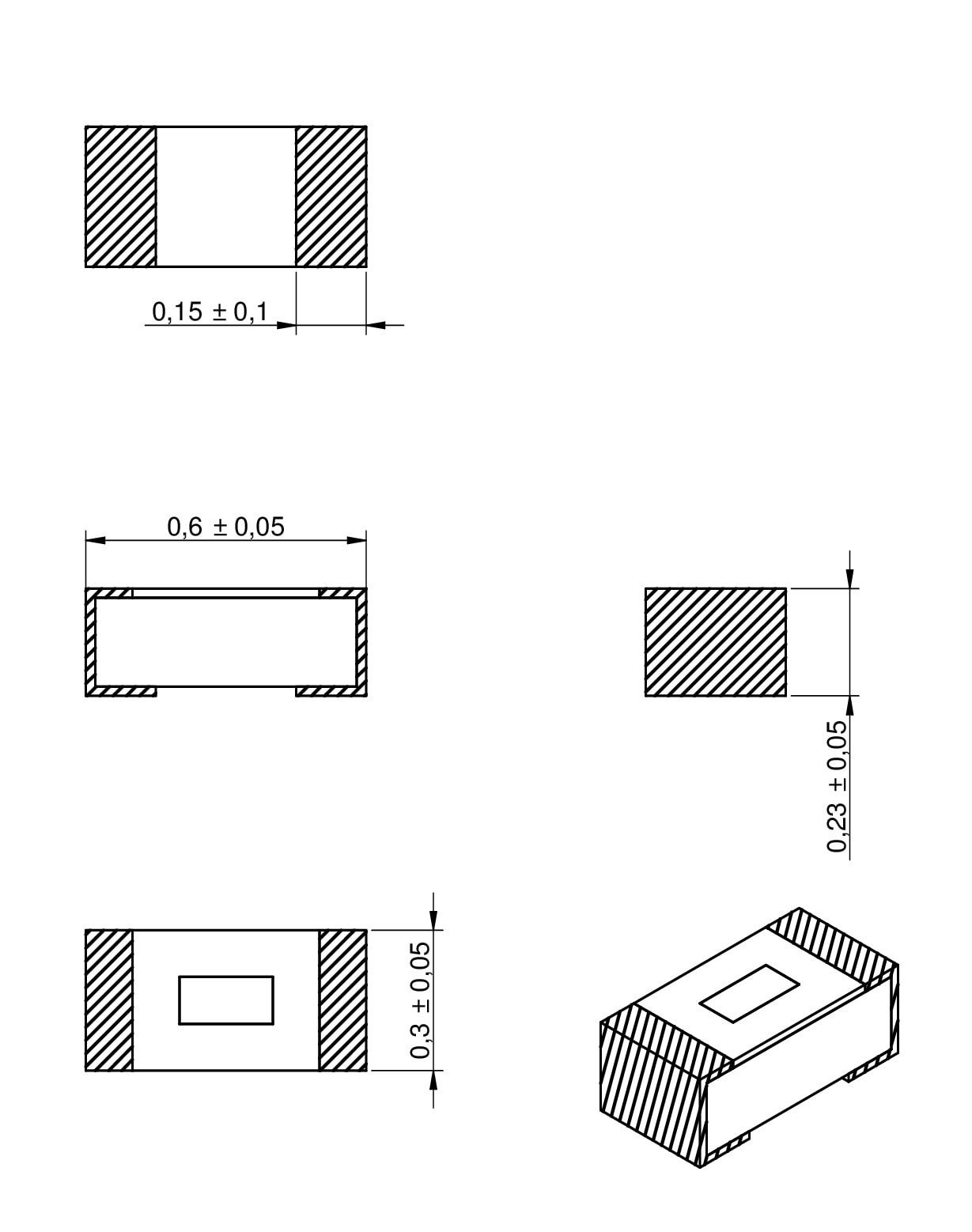
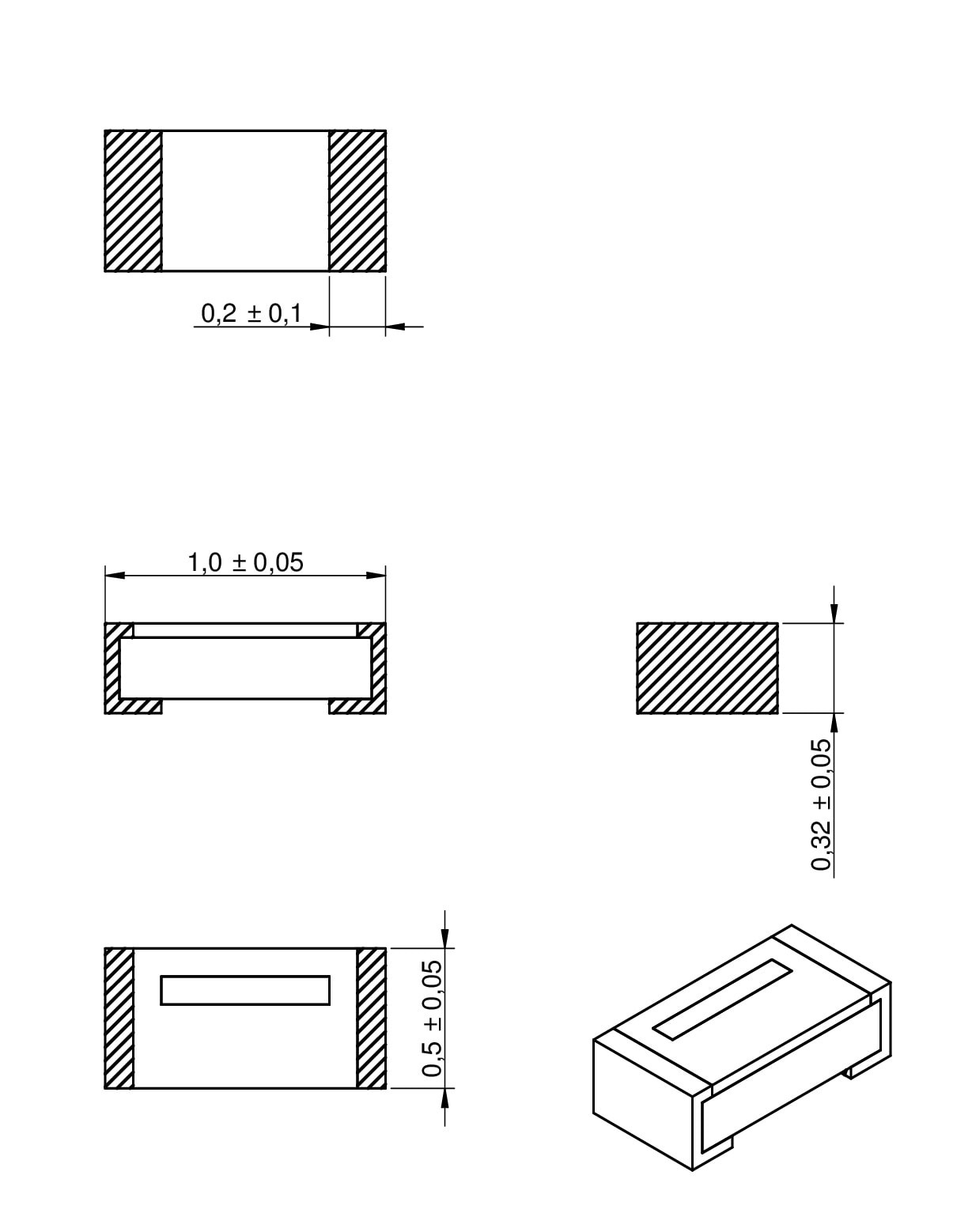
| Size | Dimensions | L (mm) | W (mm) | H (mm) | Mount | ||
|---|---|---|---|---|---|---|---|
| 0201 | 0.6 | 0.3 | 0.23 | SMT | |||
| EXT. | 0402 | 1 | 0.5 | 0.32 | SMT |
LTSpice files
Characteristics
- High self resonant frequency
- Tight tolerances of 2% (1% on request) or ± 0.1 nH and small inductance values
- Outstanding temperature stability
- In high frequency circuit the inductance is very stable
- Small inductance values
- Recommended solder profile: Reflow
- Operating temperature: –40 ºC to +125 ºC
Applications
- Mobile phone
- Pagers
- GPS products
- Wireless LAN
- Communication appliances
- RF Transceiver Module
Application Notes
Products
All
0201
0402
| Order Code | Datasheet | Simulation | Downloads | L (nH) | Tol. L | Test Condition L | Qmin. | Test Condition Q | RDC max. (Ω) | IR (mA) | fres (GHz) | Samples | |
|---|---|---|---|---|---|---|---|---|---|---|---|---|---|
| 744900010 | SPEC | 9 files | 1 | ±0.2nH | 500 MHz | 8 | 500 MHz | 0.3 | 300 | 9 | |||
| NEW | 744901010 | SPEC | 10 files | 1 | ±0.1nH | 500 MHz | 13 | 500 MHz | 0.1 | 700 | – | ||
| 744900012 | SPEC | 9 files | 1.2 | ±0.2nH | 500 MHz | 8 | 500 MHz | 0.35 | 300 | 9 | |||
| NEW | 744901012 | SPEC | 10 files | 1.2 | ±0.1nH | 500 MHz | 13 | 500 MHz | 0.1 | 700 | – | ||
| 744900013 | SPEC | 9 files | 1.3 | ±0.2nH | 500 MHz | 8 | 500 MHz | 0.45 | 250 | 9 | |||
| 744900014 | SPEC | 9 files | 1.4 | ±0.2nH | 500 MHz | 8 | 500 MHz | 0.45 | 250 | 9 | |||
| 744900015 | SPEC | 9 files | 1.5 | ±0.2nH | 500 MHz | 8 | 500 MHz | 0.45 | 250 | 9 | |||
| NEW | 744901015 | SPEC | 10 files | 1.5 | ±0.1nH | 500 MHz | 13 | 500 MHz | 0.2 | 700 | – | ||
| 744900018 | SPEC | 9 files | 1.8 | ±0.2nH | 500 MHz | 8 | 500 MHz | 0.55 | 200 | 9 | |||
| NEW | 744901018 | SPEC | 10 files | 1.8 | ±0.1nH | 500 MHz | 13 | 500 MHz | 0.2 | 560 | – | ||
| 744900019 | SPEC | 9 files | 1.9 | ±0.2nH | 500 MHz | 8 | 500 MHz | 0.55 | 200 | 9 | |||
| 744900020 | SPEC | 9 files | 2 | ±0.2nH | 500 MHz | 8 | 500 MHz | 0.7 | 200 | 8 | |||
| 744900022 | SPEC | 9 files | 2.2 | ±0.2nH | 500 MHz | 8 | 500 MHz | 0.7 | 200 | 8 | |||
| NEW | 744901022 | SPEC | 10 files | 2.2 | ±0.1nH | 500 MHz | 13 | 500 MHz | 0.3 | 440 | – | ||
| 744900027 | SPEC | 9 files | 2.7 | ±0.2nH | 500 MHz | 8 | 500 MHz | 0.8 | 150 | 8 | |||
| NEW | 744901027 | SPEC | 10 files | 2.7 | ±0.1nH | 500 MHz | 13 | 500 MHz | 0.3 | 440 | – | ||
| 744901030 | SPEC | 11 files RF & Microwave simulation modelsDownload all 11 files as zip archive | 3 | ±0.1nH | 500 MHz | 13 | 500 MHz | 0.45 | 380 | 6 | |||
| 744900033 | SPEC | 9 files | 3.3 | ±0.2nH | 500 MHz | 8 | 500 MHz | 1 | 150 | 6 | |||
| NEW | 744901033 | SPEC | 10 files | 3.3 | ±0.1nH | 500 MHz | 13 | 500 MHz | 0.4 | 380 | – | ||
| 744901036 | SPEC | 6 files | 3.6 | ±0.1nH | 500 MHz | 13 | 500 MHz | 0.55 | 380 | 6 | |||
| 744900039 | SPEC | 9 files | 3.9 | ±0.2nH | 500 MHz | 8 | 500 MHz | 1.2 | 150 | 6 | |||
| NEW | 744901039 | SPEC | 10 files | 3.9 | ±0.1nH | 500 MHz | 13 | 500 MHz | 0.5 | 340 | – | ||
| 744901043 | SPEC | 10 files | 4.3 | ±0.1nH | 500 MHz | 13 | 500 MHz | 0.65 | 320 | 6 | |||
| 744900047 | SPEC | 9 files | 4.7 | ±0.2nH | 500 MHz | 8 | 500 MHz | 1.4 | 130 | 6 | |||
| NEW | 744901047 | SPEC | 10 files | 4.7 | ±0.1nH | 500 MHz | 13 | 500 MHz | 0.6 | 320 | – | ||
| 744901051 | SPEC | 9 files | 5.1 | ±0.1nH | 500 MHz | 13 | 500 MHz | 0.75 | 300 | 6 | |||
| 744900056 | SPEC | 9 files | 5.6 | ±2% | 500 MHz | 8 | 500 MHz | 1.8 | 130 | 4 | |||
| NEW | 744901056 | SPEC | 10 files | 5.6 | ±0.1nH | 500 MHz | 13 | 500 MHz | 0.7 | 280 | – | ||
| 744901058 | SPEC | 10 files | 5.8 | ±0.1nH | 500 MHz | 13 | 500 MHz | 0.85 | 280 | 6 | |||
| 744901062 | SPEC | 10 files | 6.2 | ±0.1nH | 500 MHz | 13 | 500 MHz | 0.9 | 270 | 6 | |||
| 744900068 | SPEC | 6 files | 6.8 | ±2% | 500 MHz | 8 | 500 MHz | 2.3 | 110 | 4 | |||
| NEW | 744901068 | SPEC | 10 files | 6.8 | ±0.1nH | 500 MHz | 13 | 500 MHz | 0.9 | 260 | – | ||
| 744901072 | SPEC | 6 files | 7.2 | ±0.1nH | 500 MHz | 13 | 500 MHz | 1.05 | 260 | 6 | |||
| 744900082 | SPEC | 6 files | 8.2 | ±2% | 500 MHz | 8 | 500 MHz | 3 | 110 | 3 | |||
| NEW | 744901082 | SPEC | 10 files | 8.2 | ±0.1nH | 500 MHz | 13 | 500 MHz | 1.1 | 220 | – | ||
| 744901091 | SPEC | 9 files | 9.1 | ±0.1nH | 500 MHz | 13 | 500 MHz | 1.25 | 220 | 5.5 | |||
| 744900110 | SPEC | 6 files | 10 | ±2% | 500 MHz | 8 | 500 MHz | 3.5 | 80 | 2 | |||
| NEW | 744901110 | SPEC | 10 files | 10 | ±2% | 500 MHz | 13 | 500 MHz | 1.3 | 200 | – | ||
| NEW | 744901112 | SPEC | 10 files | 12 | ±2% | 500 MHz | 13 | 500 MHz | 1.6 | 180 | – | ||
| NEW | 744901115 | SPEC | 10 files | 15 | ±2% | 500 MHz | 13 | 500 MHz | 1.8 | 130 | – | ||
| NEW | 744901118 | SPEC | 10 files | 18 | ±2% | 500 MHz | 13 | 500 MHz | 2 | 100 | – | ||
| NEW | 744901122 | SPEC | 10 files | 22 | ±2% | 500 MHz | 13 | 500 MHz | 2.6 | 90 | – | ||
| 744901127 | SPEC | 6 files | 27 | ±2% | 500 MHz | 13 | 500 MHz | 3.25 | 75 | 2.5 |
| Order Code | Datasheet | Simulation | |
|---|---|---|---|
| 744900010 | SPEC | ||
| NEW | 744901010 | SPEC | |
| 744900012 | SPEC | ||
| NEW | 744901012 | SPEC | |
| 744900013 | SPEC | ||
| 744900014 | SPEC | ||
| 744900015 | SPEC | ||
| NEW | 744901015 | SPEC | |
| 744900018 | SPEC | ||
| NEW | 744901018 | SPEC | |
| 744900019 | SPEC | ||
| 744900020 | SPEC | ||
| 744900022 | SPEC | ||
| NEW | 744901022 | SPEC | |
| 744900027 | SPEC | ||
| NEW | 744901027 | SPEC | |
| 744901030 | SPEC | ||
| 744900033 | SPEC | ||
| NEW | 744901033 | SPEC | |
| 744901036 | SPEC | ||
| 744900039 | SPEC | ||
| NEW | 744901039 | SPEC | |
| 744901043 | SPEC | ||
| 744900047 | SPEC | ||
| NEW | 744901047 | SPEC | |
| 744901051 | SPEC | ||
| 744900056 | SPEC | ||
| NEW | 744901056 | SPEC | |
| 744901058 | SPEC | ||
| 744901062 | SPEC | ||
| 744900068 | SPEC | ||
| NEW | 744901068 | SPEC | |
| 744901072 | SPEC | ||
| 744900082 | SPEC | ||
| NEW | 744901082 | SPEC | |
| 744901091 | SPEC | ||
| 744900110 | SPEC | ||
| NEW | 744901110 | SPEC | |
| NEW | 744901112 | SPEC | |
| NEW | 744901115 | SPEC | |
| NEW | 744901118 | SPEC | |
| NEW | 744901122 | SPEC | |
| 744901127 | SPEC |
| Samples |
|---|
| Order Code | Datasheet | Simulation | Downloads | L (nH) | Tol. L | Test Condition L | Qmin. | Test Condition Q | RDC max. (Ω) | IR (mA) | fres (GHz) | Samples |
|---|