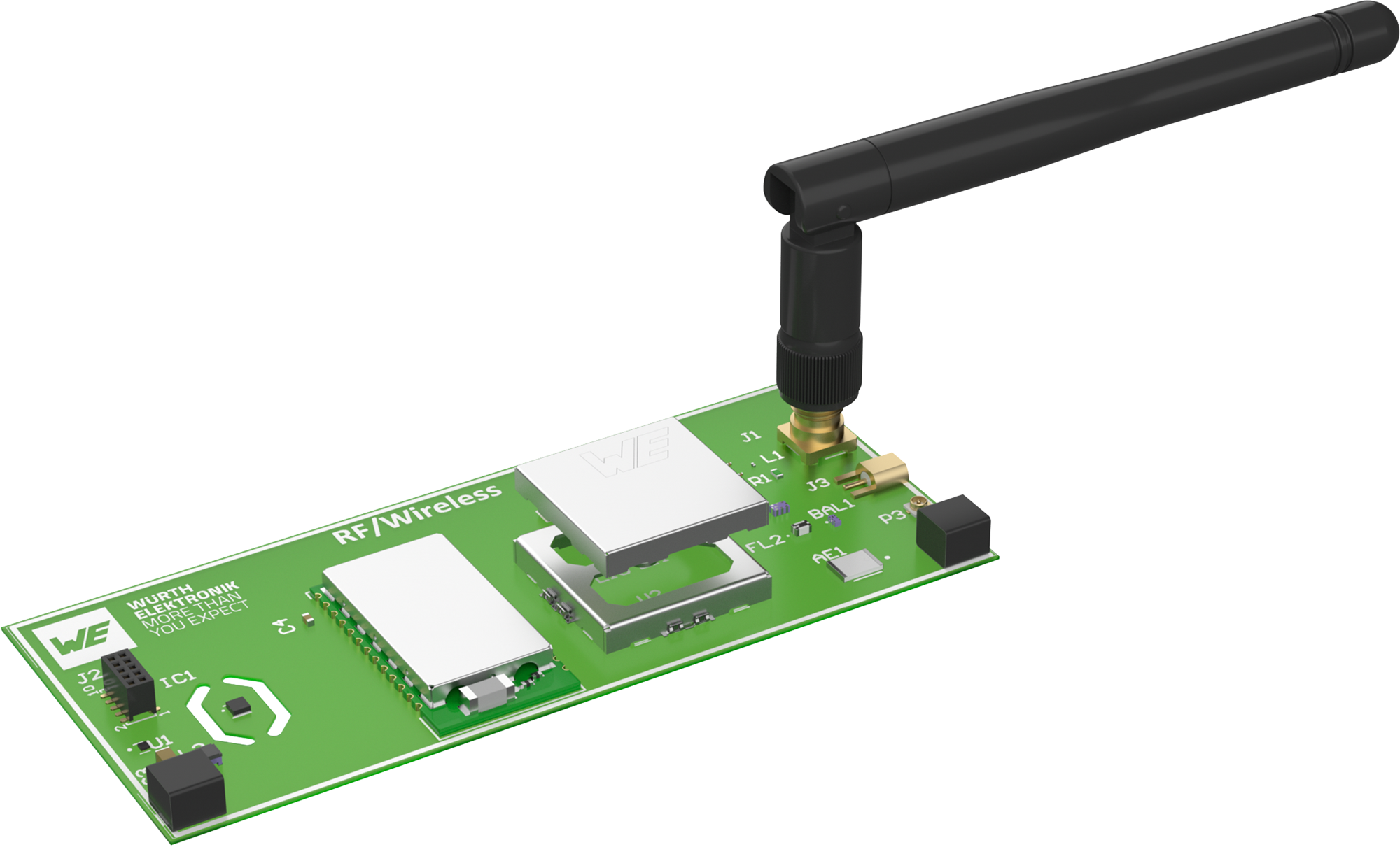
RF & Wireless Communication
Complete Modules
A radio module with the appropriate radio protocol can be selected depending on the requirements for frequency, range, environmental conditions, data rates and available electric power.
Shielding Cabinets
In the near field of an electric noise source the electric field has a high impedance. A low impedant shielding cabinet covering the critical component will act as a sacrificial capacitor plate to divert to noise back to its reference ground.
MLCCs
RF Inductors
An RF Inductor is a specialized type of inductor designed to operate efficiently at radio frequencies (RF), typically ranging from a few MHz to several GHz. These components are crucial in wireless communication systems, RF filters, oscillators, and impedance matching networks.
Antennas
If a radio module is installed in a conductive casing, for example to protect it from EMC or to use a robust metal casing, the RF signal can be routed through the casing via SMA coaxial connectors. A rod antenna with an SMA connector is ideally suited for mounting on the casing.
RF Connectors
UMRF connectors offer electromechanical connections between PCBs in a small constricted space, efficient matching and EoL testing of the chip antenna.
The SMA coaxial connector connects the rod antenna to the PCB electromechanically.
Filters & Baluns
A Balun (short for Balanced-Unbalanced) is a type of transformer used to convert between balanced and unbalanced signals. This is crucial in RF systems where antennas (balanced) need to interface with transmission lines or circuits (unbalanced).
An RF filter is a passive electronic component that allows certain frequencies to pass while blocking others. It helps eliminate unwanted signals and noise, ensuring clean and reliable communication.
Quartz Crystals & Oscillators
Place the crystal (XTAL) as close as possible to the IC. If feasible, connect the crystal housing to GND. A via fence helps reduce coupling to the ground plane. Alternatively, an oscillator can be used.
Topologies

Short Introduction to RF & Wireless Communication
For the transmission, the signal will be modulated on a carrier signal, mostly sine with constant amplitude. Thereby, the amplitude or frequency will be adopted in the rhythm of the transmitted signal. The modulated wave is radiated by an antenna and received on the other side with an antenna too. Due to demodulation at the receiver, the transmitted signal can be used.
Depending on the selected frequency or radio technology, the data rate, read range, and duty cycle may vary.
Learn More About RF & Wireless Communication


-

Multilayer chip baluns are frequently used in RF frontends. The signal chain typically includes a low-/band-pass filter and an impedance matching network between the RF chip and the antenna. An unbalanced signal is converted into a balanced signal.

-
 signal is transformed into a differential (balanced) signal.")
A balun converts an unbalanced signal into a differential, balanced signal.
 signal is transformed into a differential (balanced) signal.")
-

Chip bandpass and low-pass filters are frequently used in RF frontends. The signal chain typically includes a balun and an impedance matching network between the RF chip and the antenna.

-

With the help of the Smith chart, an impedance matching network for an antenna can be determined. For this purpose, you can use the Antenna Matching Design Kit 748001. The kit contains WE-MCA chip antennas, WE-MK ceramic multilayer inductors of size 0402, WE-MLCC high-frequency chip capacitors of size 0402, and WR-CXARY RF coaxial cables for frequencies up to 18 GHz.

-

Würth Elektronik offers two types of chip antennas, electrical and magnetic. The table shows the respective advantages and disadvantages as well as the areas of application.

-

The frequency/impedance diagram shows the self-resonant frequencies of the MLCC capacitor types with 100 nF, 10 nF, and 1 nF. The self-resonant frequencies increase as the capacitances decrease.

-

The capacitance of a capacitor is typically also dependent on an applied direct current voltage (DC Bias) and can become significantly lower with increasing voltage. From the DC Bias/capacitance diagram, it is clearly visible that with increasing miniaturization of the component, the nominal value of 470 nF decreases (red curve).

-

For applications with high mechanical stress, it is advisable to use soft termination capacitors. These have a termination with Ag-polymer/Ni/Si and minimize the risk of cracks occurring.

-

Capacitors should maintain their capacitance as consistently as possible across temperature variations. Three of the materials used, NP0, X7R, and X5R, fulfill this requirement significantly better than Y5V, as can be clearly seen in the diagram. NP0 shows virtually no changes in capacitance over a wide operating temperature range.

-

EMC enclosures shield disruptive components and areas within a device, or protect sensitive areas from external electromagnetic influences. The flowchart assists you in selecting the appropriate shielding enclosure.

-

A typical oscillator circuit consists of the crystal oscillator and the two load capacitors C1 and C2. To determine the capacitive load, the stray capacitance of the PCB and the IC pins must also be considered.

-

Considerations for the layout of an oscillator circuit: The ground plane should be under the crystal and connected to its casing. Do not place vias on the trace to the crystal. Critical signals should be placed as far away as possible from the oscillator circuit.
