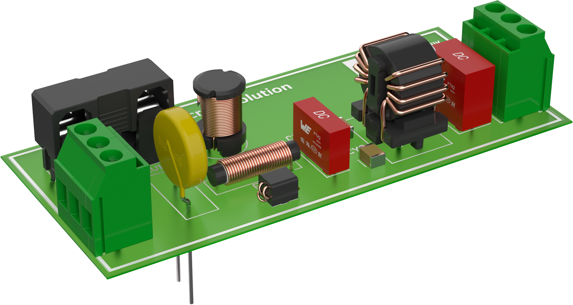
Mains Filter
Surge Protection
Disk Varistors can protect your circuit against overvoltage events such as surges and bursts. For mains applications against overvoltage events such as surges and bursts.
Common Mode Chokes
A common mode choke filters not only conducted common-mode noise but also differential-mode noise by utilizing its stray inductance. Manganese-Zinc is the standard core material for this application but for broad band EMI nickel-zinc or nanocrystalline cores may also be used.
X Capacitors
X capacitors are used between phase and neutral and thus filters differential-mode interference by means of their frequency-dependent impedance. For mains applications, higher safety standards are required, certified by ENEC, UL, and CQC.
Y-Capacitors
Y-capacitors divert common mode noise from both line and neutral to protective earth potential.
Fuse Holder
Line Filter
Differential mode noise <30 MHz is best attenuated by ferrite based chokes.
Terminal Blocks
Terminal block connectors (TBL) provide a secure and reliable way to connect wires in mains line assemblies. They allow for quick installation, safe handling of high-voltage connections, and flexible wiring options. Their robust design ensures durable connections for industrial devices.
Filter Chokes
Short Introduction to Mains Filters
A mains filter reduces interference between the device and mains line. This prevents noise coupling from the mains line into the device (increasing immunity) and vice versa (decreasing emissions).
To filter both common-mode and differential-mode noise, a common-mode choke is supplemented with X and Y capacitors. The bandwidth of the filter can be increased by adding a second choke with a different core material.
Overvoltage protection and a fuse should be placed at the input stage of the filter.
Learn More About Mains Filters


In the suppression of EMI signals, capacitors, known as X and Y capacitors, are also used. Depending on the frequency, the impedance of a capacitor varies by several orders of magnitude, as can be seen in the logarithmic visualization. Regardless of the capacitors's capacitance, the impedance curves are qualitatively similar. However, the capacitances do influence the respective frequencies of the impedance minima.

In the suppression of EMI noise signals, capacitors are used as so-called X and Y capacitors. On the left side of the image, voltage ripples from the AC power source are visible, which prevent a clean signal waveform. On the right, a clean sine wave is shown, which has been smoothed after filtering the voltage ripples of the AC power source with interference suppression capacitors.

Harsh environments with high temperatures and high humidity can degrade the dielectric layers in capacitors, thereby reducing their capacitance. The table shows the test classes from 1 to 6 and under which conditions - duration, temperature, and relative humidity - the capacitors were tested at nominal voltage.