IC Peripherals
On Board Shielding
In the nearfield of the IC, the emitted electrical field has a rather high impedance. A conductive enclosure with low impedant paths to ground is well suited to shield it.
Quartz Crystals & Oscillators
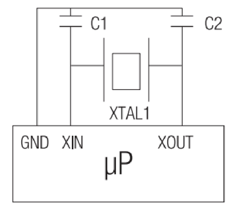
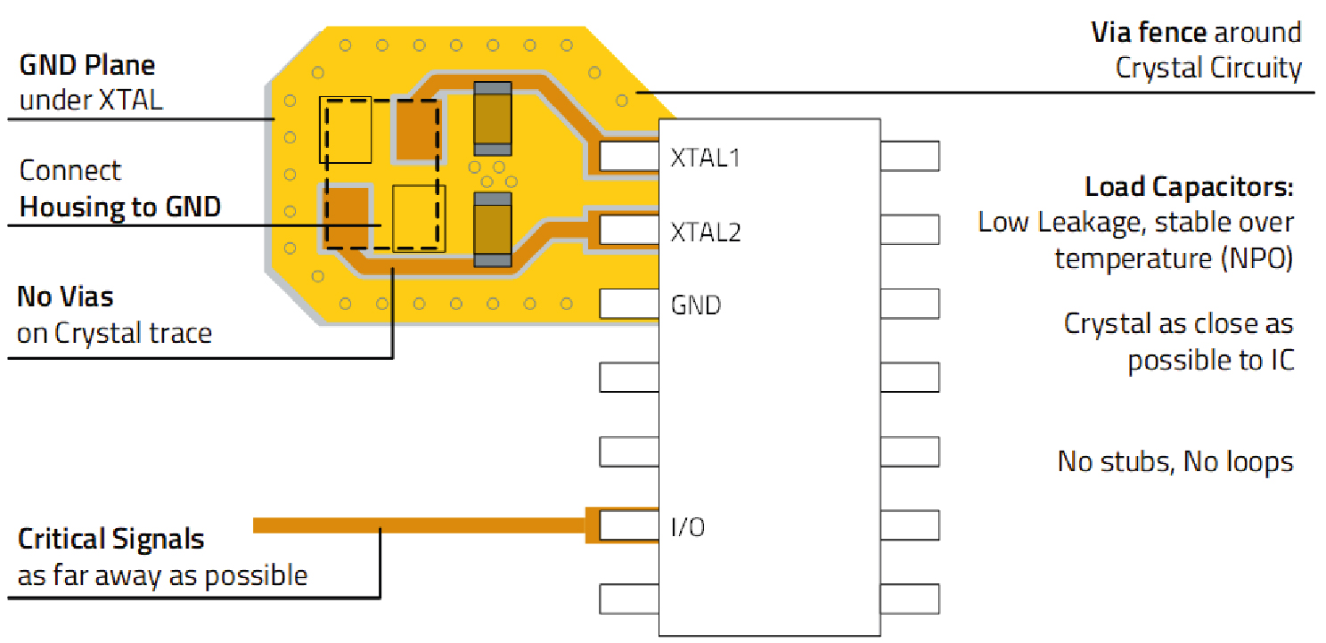
Keep the XTAL as close as possible to the IC. Where applicable connect the XTAL housing to GND. A via fence reduces coupling to the GND plane. An oscillator can be used alternatively.
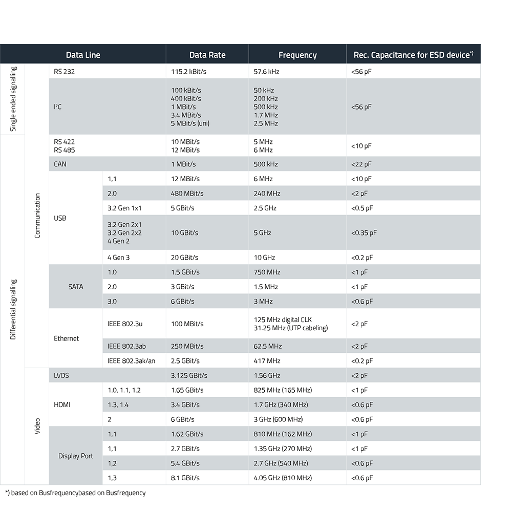
ESD Protection
Thermal Management Solutions
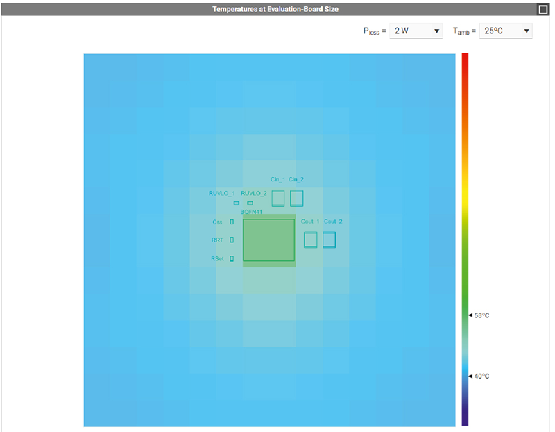
Thermal Management is of importance in order to guarantee reliability and longevity of electronic devices and components.
Configuration Switch
MLCCs
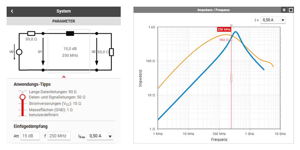
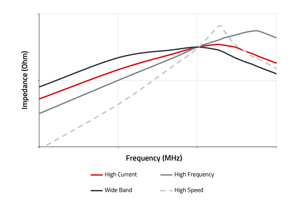
SMT Ferrites
On single ended datalines you can use a High Speed SMD Ferrite to improve EMC.
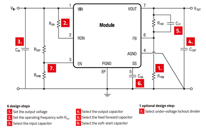
Point of Load Regulator
Programming Interface Connector
Pin Header & Socket Header

Short Introduction to IC Peripherals
No application works without integrated circuits, and no integrated circuit works without peripherals. These external components are crucial for enabling communication, power management, and control.
In this overview you will find typical components for the circuitry of microprocessors and controllers. These include power supplies, filters, programming connectors, indicator LEDs and thermal management.
Learn More About IC Peripherals
-
When protecting against electrostatic discharge (ESD), a sensitive electronic component (Load) is safeguarded by a parallel discharge path (VDR), which becomes conductive when the breakdown voltage of the protective element (VDR) is reached. In this way, the overvoltage (Transient) does not reach the sensitive load (Load), which would exceed the threshold for system failure, but is instead "clamped" to the clamping voltage.
-
To prevent the coupling of ESD pulses and to reduce electromagnetic interference, components for ESD protection should be placed as close as possible to the entry point.
-
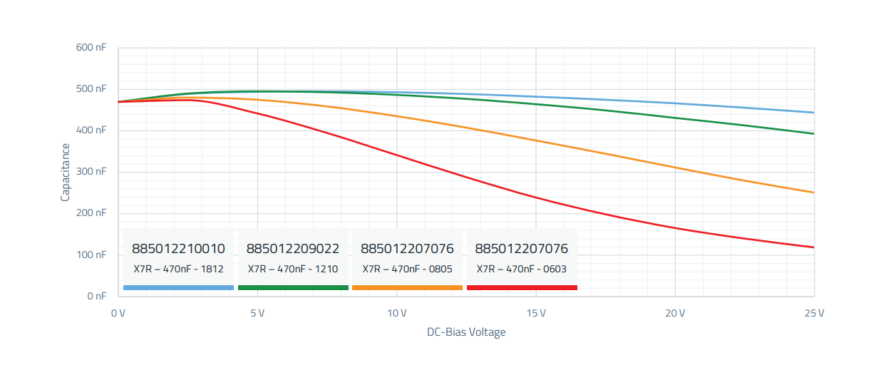
The capacitance of a capacitor is typically also dependent on an applied direct current voltage (DC Bias) and can become significantly lower with increasing voltage. From the DC Bias/capacitance diagram, it is clearly visible that with increasing miniaturization of the component, the nominal value of 470 nF decreases (red curve).
-
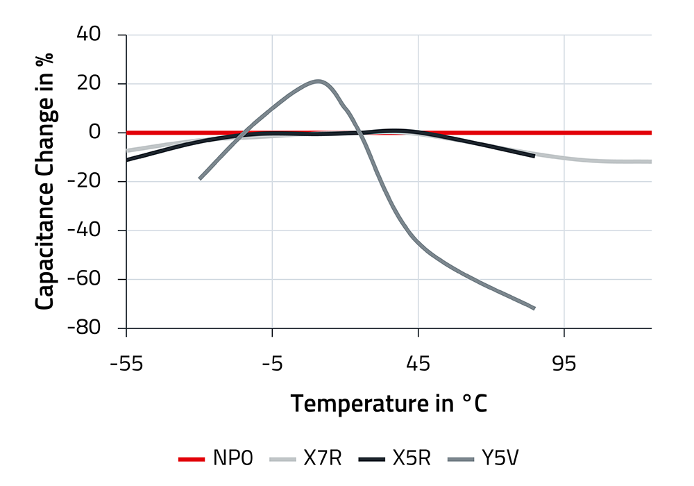
Capacitors should maintain their capacitance as consistently as possible across temperature variations. Three of the materials used, NP0, X7R, and X5R, fulfill this requirement significantly better than Y5V, as can be clearly seen in the diagram. NP0 shows virtually no changes in capacitance over a wide operating temperature range.


