DC Filters
Capacitors
In a DC input filter, electrolytic capacitors can help prevent ringing and dampen oscillations due to their ESR characteristics. With capacitance values in the range of several hundred µF, they can also act as buffer elements.
Overvoltage Protection
Multilayer Varistors are capable of diverting high currents, but with a rather high clamping voltage. For semiconductor-based overvoltage protection, e.g., TVS diodes, the clamping voltage lies close to the operating voltage, but the power dissipation is lower. Therefore, a two-stage protection concept is often useful.
PCB Ferrites
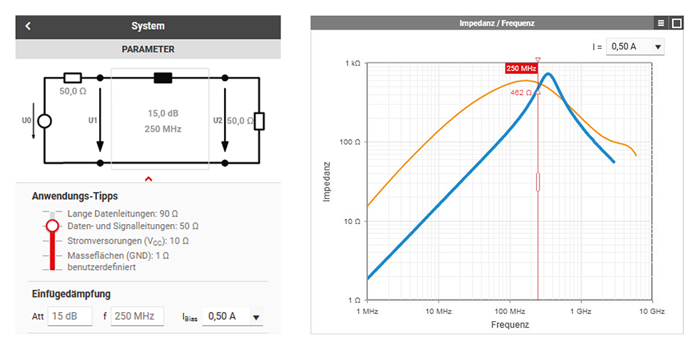
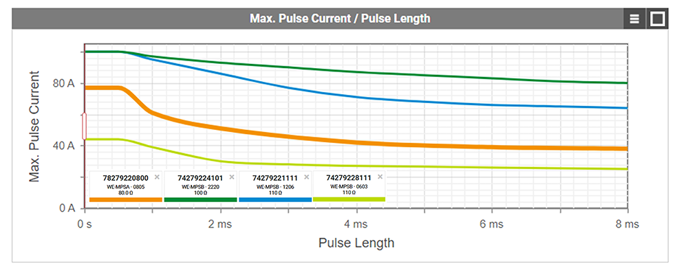
SMD ferrites capable of handling high inrush currents are suitable for applications requiring effective EMI suppression.
MLCC & Aluminium Polymer Capacitor
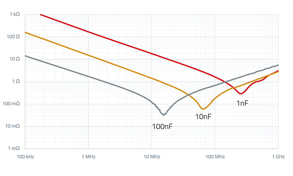
Keep the effects of DC bias and SRF in mind when selecting MLCCs for filtering. Film capacitors don’t have a DC bias but they require significantly more space in the design.
DC & Data Line Chokes
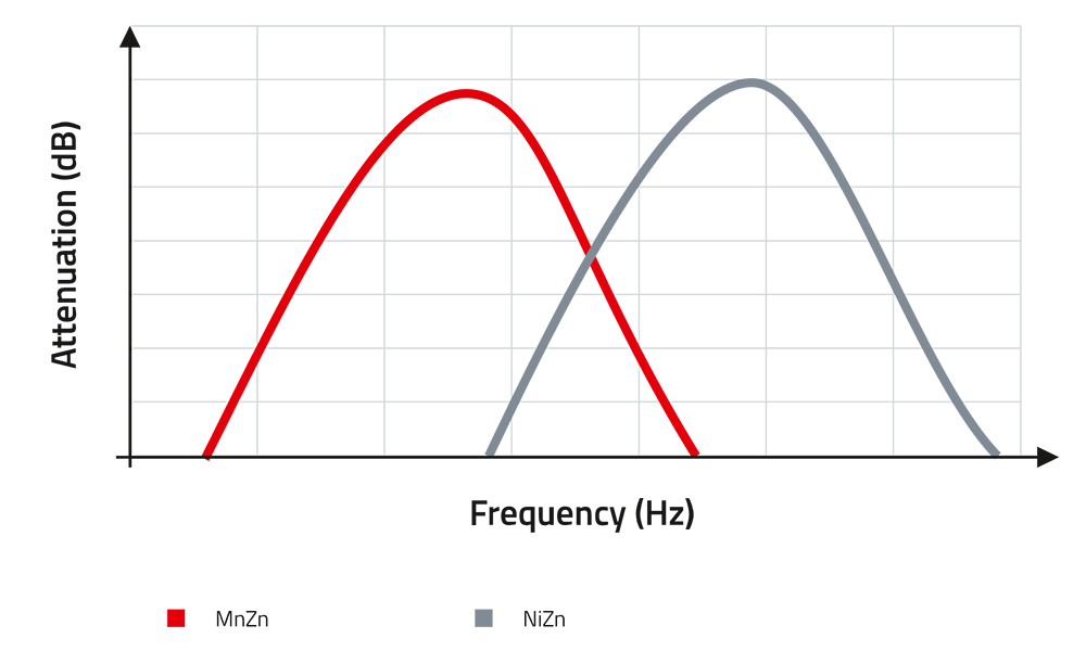
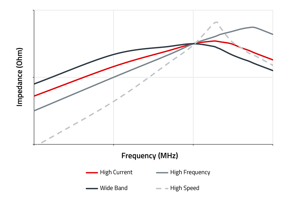
Differential mode noise <30 MHz is best attenuated by ferrite chokes.

Short Introduction to DC Filter
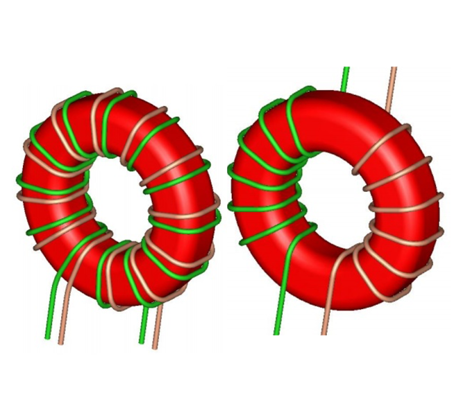
A DC input filter acts as a barrier against electrical noise, protecting both the device and its power source. It blocks unwanted noise from entering the device (boosting immunity) and stops the device from polluting the supply line (reducing emissions). To tackle both common-mode and differential-mode noise, a common-mode choke is paired with line filters and capacitors. If overvoltage protection is required, it belongs right at the filter’s input.
Learn More About DC Filter
-
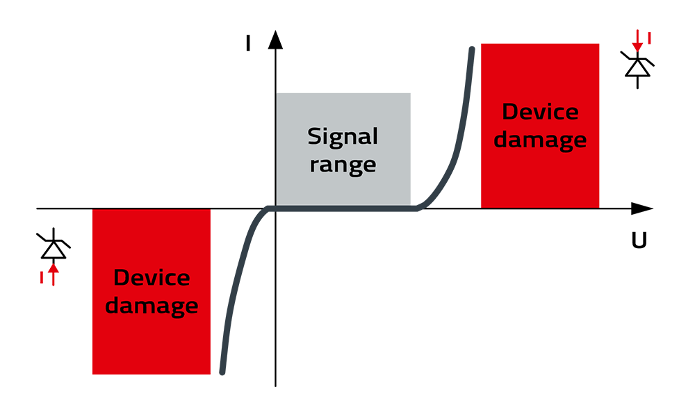
Characteristic curve for a unidirectional overvoltage protection device: During normal operation, the signal should remain within the voltage range depicted in gray. If the voltage continues to rise, excess currents are initially diverted and the voltage is clamped, before the red area is reached at even higher overloads, causing damage to the overvoltage protection device.
-
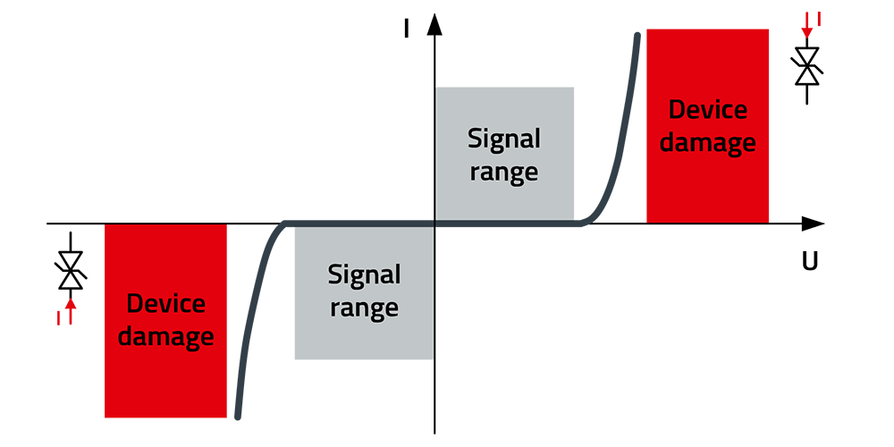
Characteristic curve for a bidirectional overvoltage protection element: Under normal operation, the signal should remain within one of the gray shaded voltage areas. If the voltage continues to increase (in either a positive or negative direction), excess currents are initially diverted and the voltage is clamped, before reaching the red area at even higher overloads, where the overvoltage protection element may become damaged.
-
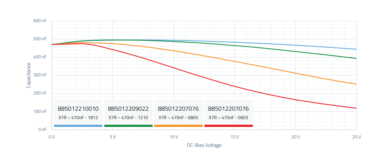
The capacitance of a capacitor is typically also dependent on an applied direct current voltage (DC Bias) and can become significantly lower with increasing voltage. From the DC Bias/capacitance diagram, it is clearly visible that with increasing miniaturization of the component, the nominal value of 470 nF decreases (red curve).
-
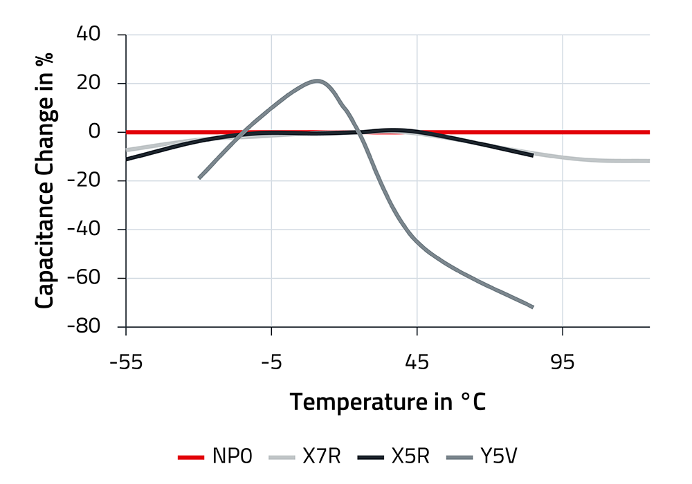
Capacitors should maintain their capacitance as consistently as possible across temperature variations. Three of the materials used, NP0, X7R, and X5R, fulfill this requirement significantly better than Y5V, as can be clearly seen in the diagram. NP0 shows virtually no changes in capacitance over a wide operating temperature range.
-
The lifespan of a capacitor depends on the maximum allowable operating temperature, the ambient temperature, the ripple current, and the applied voltage. The simplified formulas disregard the influence of current and voltage. In RedExpert, the lifespan can be calculated in detail for your application.


