Single Pair Ethernet
Crystal
Keep the XTAL as close as possible to the IC. Where applicable connect the XTAL housing to GND. A via fence reduces coupling to the GND plane. An oscillator can be used alternatively.
Load Capacitor
Load capacitors should be low leakage and stable across temperature range (NP0). For the capacitive load (cload) the stray capacitance of the PCB and the IC pins should be considered:
CL = (C1*C2) / (C1+C2) + Cstray
Cstray ≈ 3…6pF
Common Mode Filter
100BASE-T1 Applications require a common mode choke for interference suppression in frequencies up to 200 MHz.
ESD Protection
Although ethernet is an isolated interface, 1.5kV is not enough to protect from ESD. Super Speed TVS are needed to properly avoid damage to delicate parts. Avoid layer hops to prevent propagation of the ESD.
MLCC - Multilayer Ceramic Chip Capacitor 50 V
This Capacitor increases common mode rejection by balancing the center tap of the transformer.
MLCC - Multilayer Ceramic Chip Capacitor 3 kV
Isolation of 1.5 kV AC is required by the standard, which makes MLCCs with only 2 kV insufficient.
MLCC - Multilayer Ceramic Chip Capacitor 2 kV
This capacitor diverts common mode noise to Chassis Ground. Because of the capacitors dc blocking property, a rated voltage of 2 kV is chosen, to avoid inadvertent potential equalization and damaging of the component.
Signal Transformer
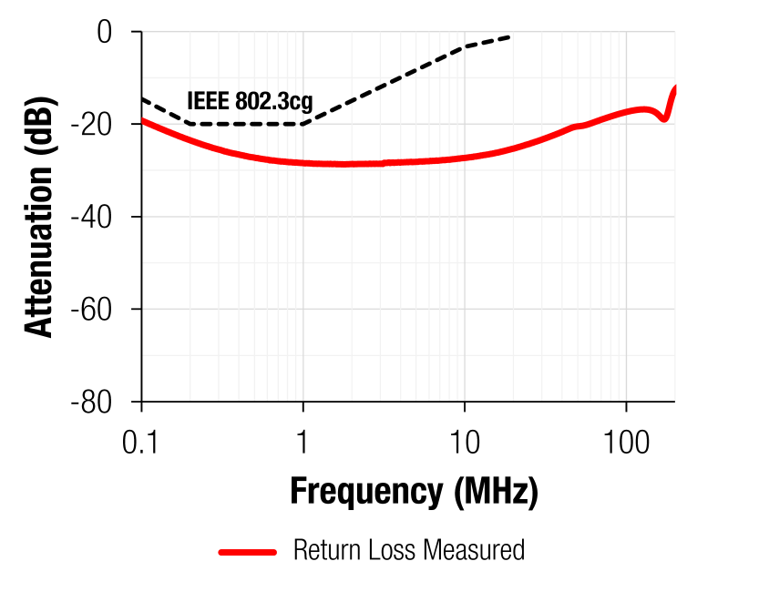
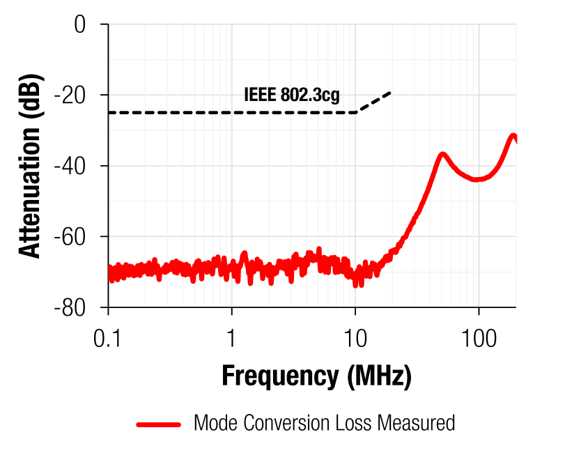
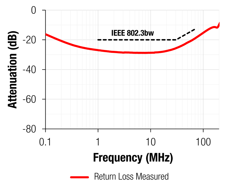
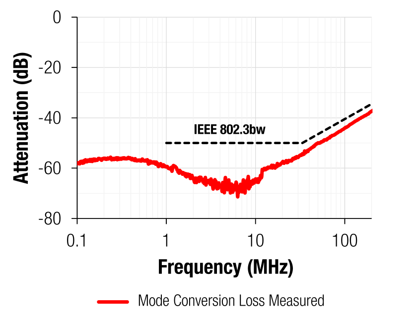
According to IEC 62368-1 Single Pair Ethernet requires an isolation of 1.5 kV. Our WE-STST transformer series combines excellent performance regarding return loss and mode conversion loss with a very compact size of only 4.5 x 3.2 mm.
MLCC - Multilayer Ceramic Chip Capacitor
These Capacitors extend the transformer bandwith and thus improve the return loss in low frequencies. As an alternative, a capacitor can be used at the center tap to block DC current from PoDL Application.
MLCC - Multilayer Ceramic Chip Capacitor
These Capacitors extend the transformer bandwith and thus improve the return loss in low frequencies. As an alternative, a capacitor can be used at the center tap to block DC current from PoDL Application.
XTAL Ground
This GND plane should be connected to IC GND and cover all the traces to the XTAL.
Grounding Scheme
RF coupling of the cable shield and PCB ground to chassis will short common mode noise in both directions.
Short Introduction to Single Pair Ethernet
Ethernet is a common interface for cabled networks.
The new standard Single Pair Ethernet (SPE), reaching up to 1000 m, enables many new use cases to replace analog sensor applications or industrial bus systems.
Besides cable length, mechanical connector stability and PCB size reduction were the drivers to create a new standard.
Würth Elektronik is a member of the SPE Industrial Partner Network
The network is an equal association of companies that promote Single Pair Ethernet technology as the basis for rapid and successful growth of the IIoT (Industrial Ethernet of Things).
Learn More About Single Pair Ethernet
One pair is all you need
Single Pair Ethernet
One pair is all you need
Single Pair Ethernet
Single Pair Ethernet embodies a new type of data transmission. Contrary to Multipair Ethernet, only two wires are needed. The small number of wires ensures thinner cable diameters and reduces cost.
By using only one pair of wires, the number of passive components on the PCB is considerably reduced. Together with the very compact connector, Single Pair Ethernet can save up to 75 % PCB space, compared to current Ethernet over RJ45.

The Advantages of Single Pair Ethernet
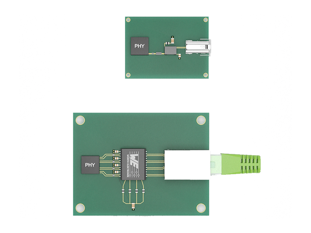
Multi Pair Ethernet vs. Single Pair Ethernet
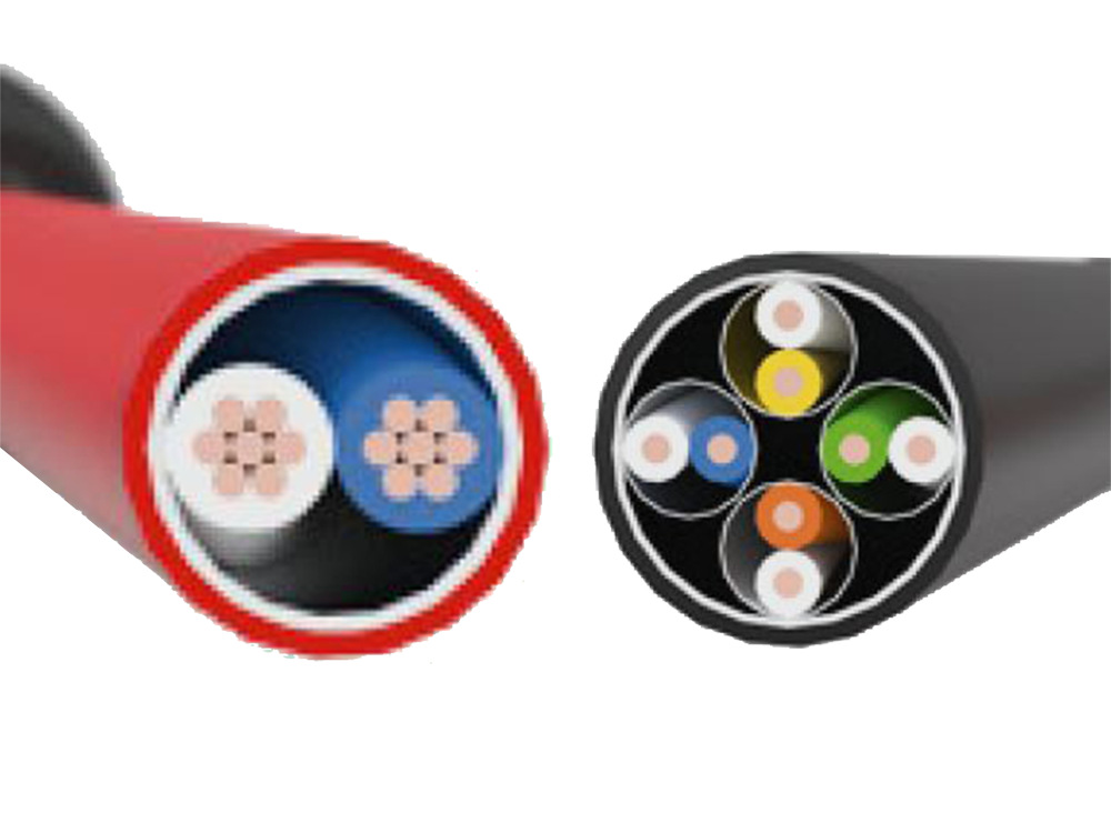
Smaller cable diameter and 30 % of weight reduction
Significantly lower space consumption on the PCB
Insulation Voltage According to IEC 62368-1
Insulation Voltage According to IEC 62368-1
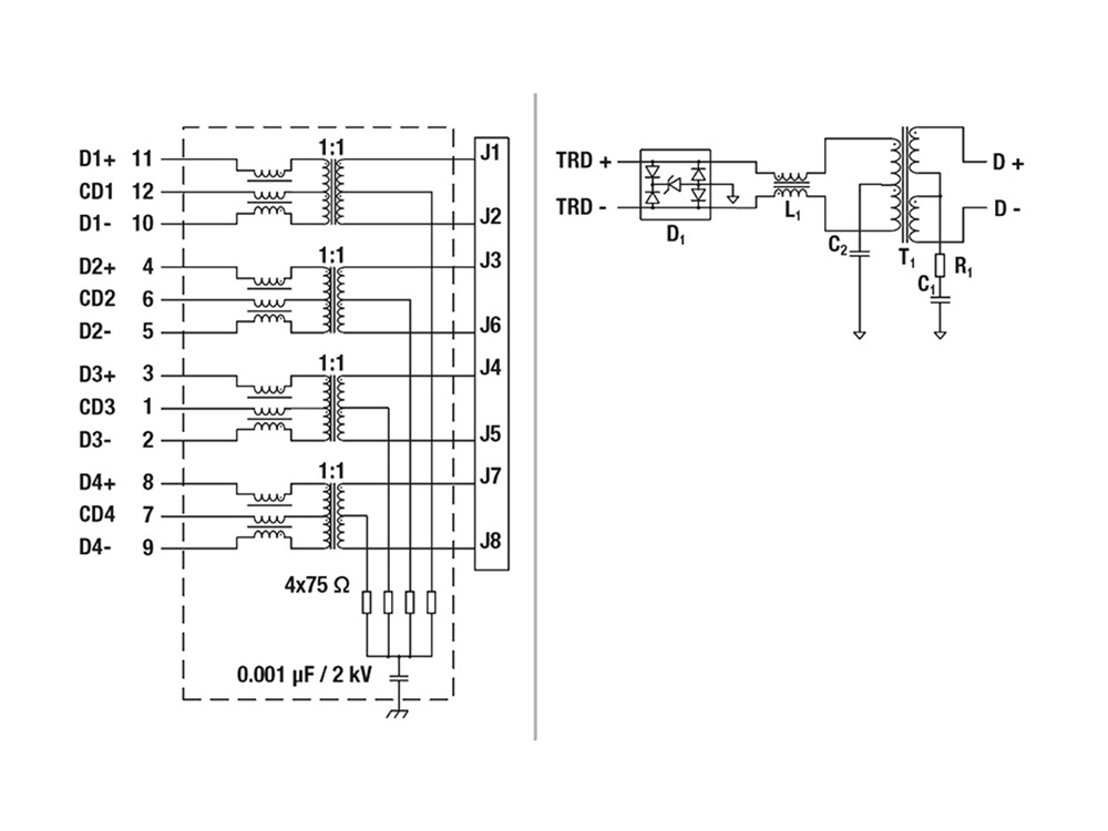
Similar to Ethernet over four-pair wires, isolation in accordance with IEC 62368-1 (formerlyIEC 60950) is also specified for Single Pair Ethernet. Capacitors with 50 Volt galvanic isolation apply almost exclusively to automotive Ethernet applications and are not sufficient for industrial applications.
The good news is that the electrical isolation in Single Pair Ethernet can be easily solved by a signal transformer. Our WE-STST transformer series combines excellent performance with a very compact size of only 4.5 x 3.2 mm.
Through connection of the centre tap to GND, common mode signals are also effectively attenuated.
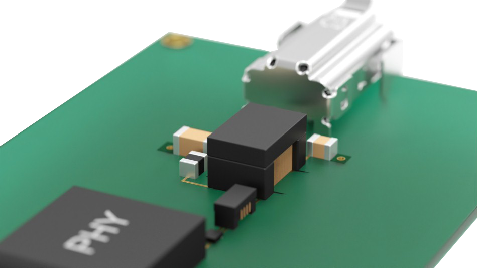
Measurement Results
