RS485 / RS422
Controller
Like any integrated circuit the controller will need some peripheral components to make it run properly
Crystal
Keep the XTAL as close as possible to the IC. Where applicable connect the XTAL housing to GND. A via fence reduces coupling to the GND plane. An oscillator can be used alternatively.
Load Capacitor
Load capacitors should be low leakage and stable across temperature range (NP0). For the capacitive load (cload) the stray capacitance of the PCB and the IC pins should be considered:
CL = (C1*C2) / (C1+C2) + Cstray
Cstray ≈ 3…6pF
Digital Isolator
Digital Isolators provide a galvanic isolation of signals and reliable data transmission in high-speed applications with rates up to 150 Mbps. The WPME-CDIx series optionally includes an isolated power supply and provides an isolation voltage of up to 5000VRMS. All part numbers are UL1577 recognized and have VDE 0884-17 and IEC 60747-17 certificates.
Isolated DC/DC Converter
The use of isolated signal lines often facilitates the need for an isolated power supply for sensors or other peripherals. Integrated power modules simplify the design and accelerate the development
Common Mode Filter
On differential datalines, a CMC filters common mode noise without affecting the useful signal.
Common Mode Filter
On differential datalines, a CMC filters common mode noise without affecting the useful signal.
ESD Protection
ESD protection devices should be put right behind the connector. Avoid layer hops to prevent propagation of the ESD.
D-SUB Connector
We can provide the well established D-Sub connector. Not only do we have the male and female version in our portfolio, but with the angled and non angled versions and fitting cable options we can fully support you and your needs.
Terminal Blocks
To further support the needs of our industrial customers we also have a wide range of Terminal Blocks. From a technical aspect we support THT, THR and SMT and we have different pitches, ranging from 2,5mm up to 7,62mm, when looking at our pluggable portfolio. To give you an overview of the fixation types we can offer: Wire Protector, Rising Cage Clamp, Excenter Clamp, Screwless Spring Clamp, Screwless Push In, Pluggable and IDC Clamp.
XTAL Ground
This GND plane should be connected to IC GND and cover all the traces to the XTAL.
Short Introduction to RS485 / RS422
The RS485 interface (Recommended Standard 485) is used for data communication over long distances. Data is transmitted bidirectionally via a pair of wires at a data rate of up to 12 Mbps. The symmetrical line increases the electromagnetic interference immunity. Since the protocol is not standardized, implementations of different manufacturers are rarely compatible with each other.
RS422 differs essentially in the use of 2 pairs of wires, each of which is used unidirectionally. Mostly 9-pole D-Sub variants are used as connectors.
Learn More About RS485 / RS422
Plug and Play!
Plug and Play!
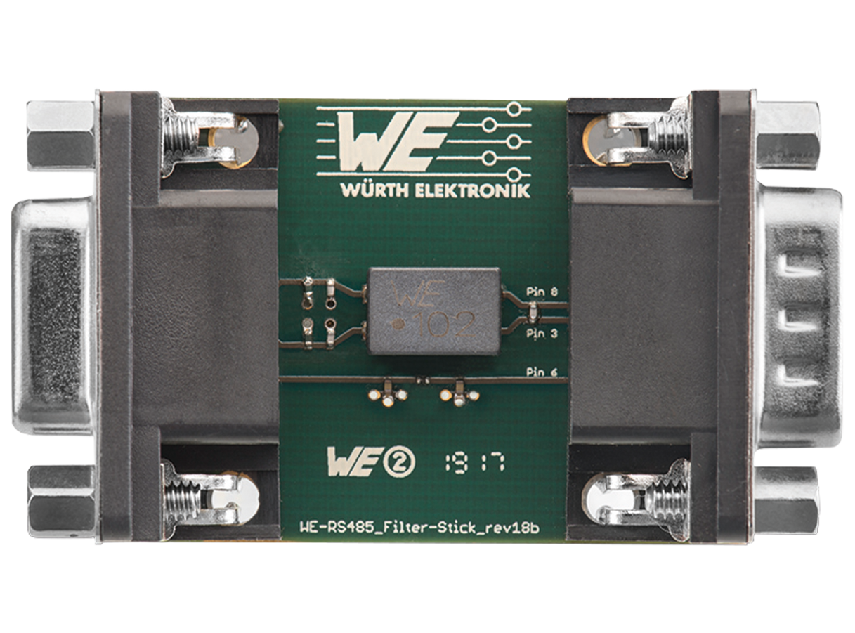
To avoid reduced integrity of the data transfer due to interference and to pass EMC tests, components matched to the data lines are necessary.
For simplified implementation, the adapter stick was designed, which contains a complete filter circuit for the selected application. The filter stick is plugged into the corresponding interface for test purposes. If the test is passed with the filter stick plugged in, the filter circuit can be integrated into the system.
1. Plug in filter stick
2. Check filter effect
3. Implement the circuit in the system

Filter Performance

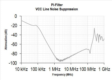
- Attenuation up to 95 dB due to pi-filter
- Protection of high frequency voltages

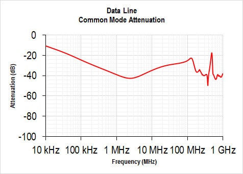
High common mode attenuation over wide frequency range due to common mode choke (WE-SL2) and Y-capacitors (WCAP-CSGP)

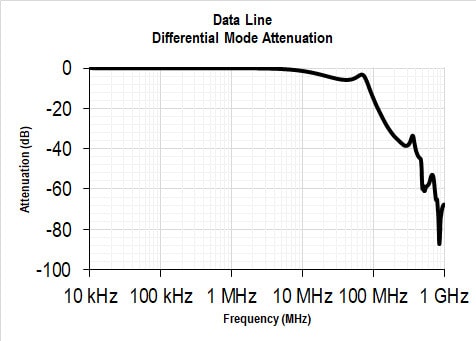
High differential mode attenuation from 6 MHz due to X-capacitor (WCAP-CSGP)
No influence on the data signal according to RS-485 standard


