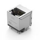
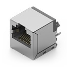
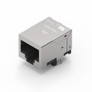
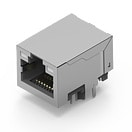
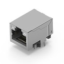
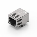
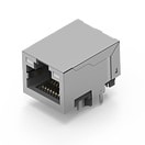
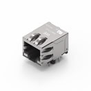
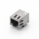
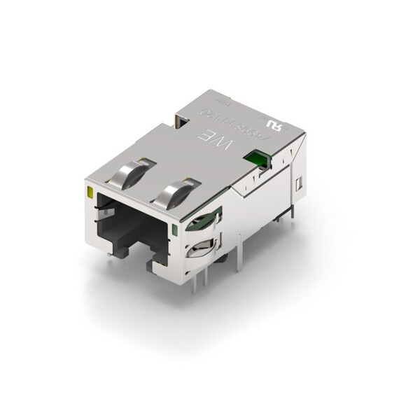
WE-RJ45 LAN Through Hole Reflow
Characteristics
- RJ45 designed to use for Pin-in-Paste soldering
- High mechanical stability through THT pins
- High Temperature LEDs
- Extra high standoff for a good thermal airflow
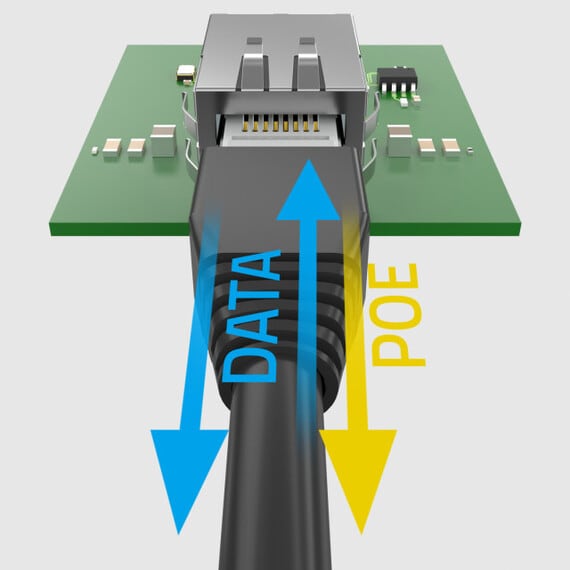
- Power over Ethernet up to 30 W
- Compliant with standard: IEEE 802.3u, IEEE 802.3ab, IEEE 802.3af, IEEE 802.3at
- Reference Designs
- RD016 Reference Design Gigabit Ethernet Front End
- RD022 GB PoE+-Ethernet-USB“ adapter for industrial use with an EMC perspective
Applications
- Suitable for industrial temperatures from –40 °C up to +85 °C
- Compatible to Industrial Ethernet systems like EtherCAT or Profinet
- Compliant with most IC’s for Ethernet applications such as Microchip, Texas Instruments, Broadcom, Linear Technology
- Hubs, Routers, Switches, IP cameras, IoT applications
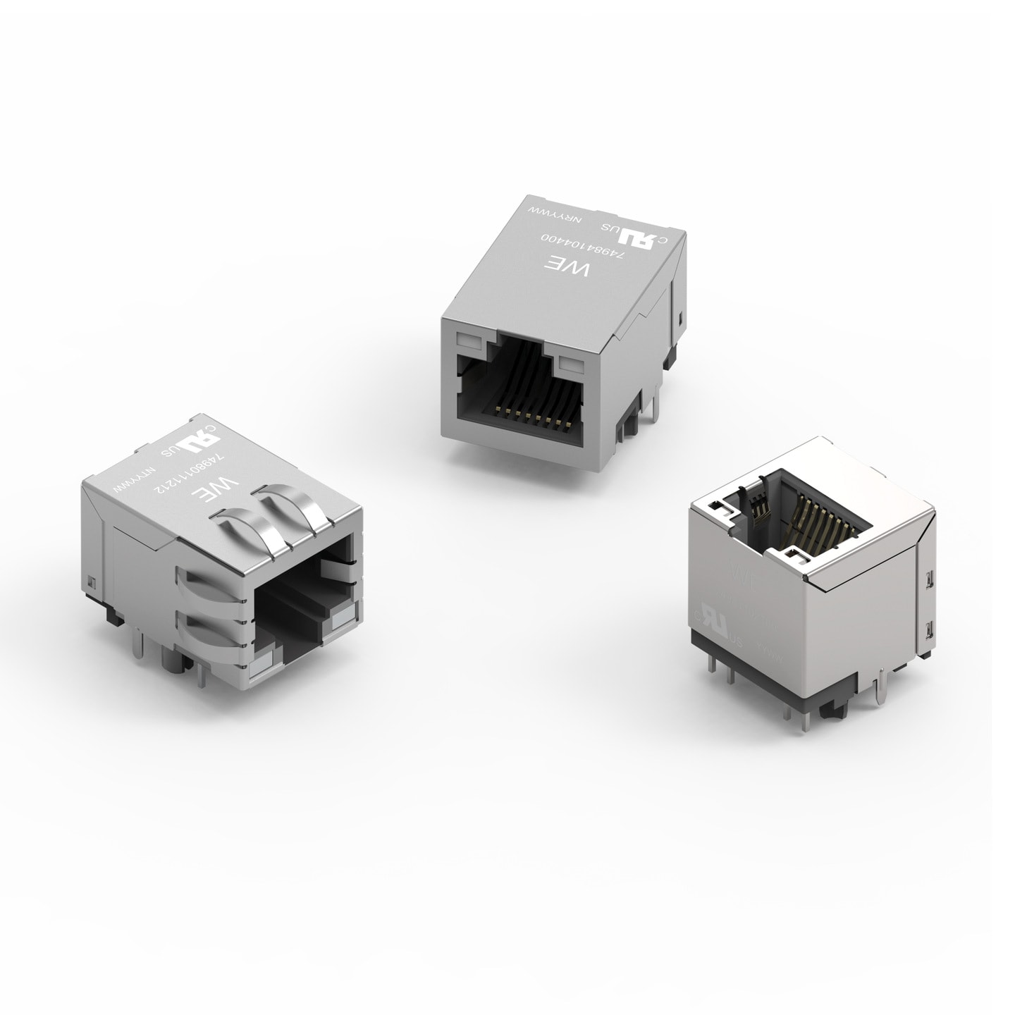
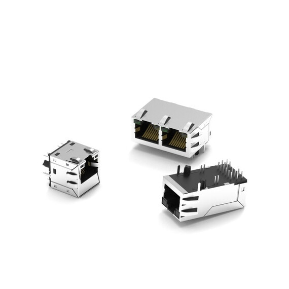
Products
Order Code | Datasheet | Simulation | Downloads | Status | Data rate | PoE | Ports | Tab | Improved CMRR | Operating Temperature | LED | PHY Chip Mode | Mount | USB | Shield Tabs | Samples | |
|---|---|---|---|---|---|---|---|---|---|---|---|---|---|---|---|---|---|
 | 74980101200 | SPEC | Status Activei| Production is active. Expected lifetime: >10 years. | Data rate10/100BASE-TX | PoEnon-PoE | Ports1 | Tab PositionVertical | Improved Common Mode RejectionNo | Operating Temperature -40 °C up to +85 °C | LED (Left-Right)yellow-green | PHY Chip Modecurrent & voltage | MountTHR | USBNo | Shield TabsNo | |||
 | 74981102100 | SPECPCN pendingDue to a pending PCN, a modification of the component will be implemented soon. Please find the PCN below. If you have further questions please get in contact with our sales staff. | Status Activei| Production is active. Expected lifetime: >10 years. | Data rate10/100/1000BASE-T | PoEnon-PoE | Ports1 | Tab PositionVertical | Improved Common Mode RejectionNo | Operating Temperature -40 °C up to +85 °C | LED (Left-Right)green-yellow | PHY Chip Modecurrent | MountTHR | USBNo | Shield TabsNo | |||
 | 74984104401 | SPEC | Status Activei| Production is active. Expected lifetime: >10 years. | Data rate10/100BASE-TX | PoEPoE+ | Ports1 | Tab PositionVertical | Improved Common Mode RejectionNo | Operating Temperature -40 °C up to +85 °C | LED (Left-Right)yellow/green-yellow/green | PHY Chip Modecurrent | MountTHR | USBNo | Shield TabsNo | |||
 | 74980100000 | SPEC | Status Activei| Production is active. Expected lifetime: >10 years. | Data rate10/100BASE-TX | PoEnon-PoE | Ports1 | Tab PositionVertical | Improved Common Mode RejectionNo | Operating Temperature -40 °C up to +85 °C | – | PHY Chip Modecurrent & voltage | MountTHR | USBNo | Shield TabsNo | |||
 | 74980100001 | SPEC | Status Activei| Production is active. Expected lifetime: >10 years. | Data rate10/100BASE-TX | PoEnon-PoE | Ports1 | Tab PositionDown | Improved Common Mode RejectionNo | Operating Temperature -40 °C up to +85 °C | – | PHY Chip Modecurrent & voltage | MountTHR | USBNo | Shield TabsNo | |||
 | 74980104400 | SPEC | Status Activei| Production is active. Expected lifetime: >10 years. | Data rate100BASE-TX | PoEnon-PoE | Ports1 | Tab PositionUp | Improved Common Mode RejectionNo | Operating Temperature -40 °C up to +85 °C | LED (Left-Right)green/yellow - green/yellow | PHY Chip Modecurrent & voltage | MountTHR | USBNo | Shield TabsNo | |||
 | 74982104400 | SPEC | Status Activei| Production is active. Expected lifetime: >10 years. | Data rate100BASE-TX | PoEPoE | Ports1x1 | Tab PositionUp | Improved Common Mode RejectionNo | Operating Temperature -40 °C up to +85 °C | LED (Left-Right)green/yellow - green/yellow | PHY Chip Modecurrent | MountTHR | USBNo | Shield TabsNo | |||
 | 74984104400 | SPEC | Status Activei| Production is active. Expected lifetime: >10 years. | Data rate100BASE-TX | PoEPoE+ | Ports1x1 | Tab PositionUp | Improved Common Mode RejectionNo | Operating Temperature -40 °C up to +85 °C | LED (Left-Right)green/yellow - green/yellow | PHY Chip Modecurrent | MountTHR | USBNo | Shield TabsNo | |||
 | 74980111212 | SPEC | Status Activei| Production is active. Expected lifetime: >10 years. | Data rate100BASE-TX | PoEnon-PoE | Ports1 | Tab PositionDown | Improved Common Mode RejectionNo | Operating Temperature -40 °C up to +85 °C | LED (Left-Right)yellow-green | PHY Chip Modecurrent & voltage | MountTHR | USBNo | Shield TabsYes | |||
 | 74981104400 | SPEC | Status Activei| Production is active. Expected lifetime: >10 years. | Data rate1000BASE-T | PoEnon-PoE | Ports1x1 | Tab PositionUp | Improved Common Mode RejectionNo | Operating Temperature -40 °C up to +85 °C | LED (Left-Right)green/yellow - green/yellow | PHY Chip Modecurrent | MountTHR | USBNo | Shield TabsNo | |||
 | 7498111123 | SPEC | Status Activei| Production is active. Expected lifetime: >10 years. | Data rate1000BASE-T | PoEnon-PoE | Ports1 | Tab PositionDown | Improved Common Mode RejectionNo | Operating Temperature -40 °C up to +85 °C | LED (Left-Right)yellow-green | PHY Chip Modecurrent | MountTHR | USBNo | Shield TabsYes | |||
 | 7498111124 | SPEC | Status Activei| Production is active. Expected lifetime: >10 years. | Data rate1000BASE-T | PoEnon-PoE | Ports1 | Tab PositionDown | Improved Common Mode RejectionNo | Operating Temperature -40 °C up to +85 °C | LED (Left-Right)yellow-green | PHY Chip Modevoltage | MountTHR | USBNo | Shield TabsYes |
WE-RJ45 LAN
WE-RJ45 LAN
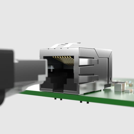
The RJ45 connector with magnetics can be quickly and easily implemented in an ethernet interface, with the integrated transformer and filter design ensuring compliance to IEEE 802.3 and IEC 62368-1 (old: IEC 60950-1) standards. For valuable board space savings, the design is 50% more compact than a discrete magnetics solution.
The filter design consists of a transformer, at least one common mode choke per channel and Bob Smith termination. Components with additional common mode chokes are available for even better common mode rejection.

Technical Details:

Still questions about the application?

The data sheet of the PHY indicates whether it is current or voltage controlled, which is an important criterion for selecting the transformer jack.
For a voltage controlled PHY, the LAN transformer is wired directly to the terminals of the PHY chip. The current mode PHY has a VDDA pin for power supply, the voltage mode PHY has no VDDA pin. Therefore the current in current mode PHYs flows via the LAN transformer pins.
Looking for the right jack for your interface? With REDEXPERT, our precise simulation platform, you can find it quickly and easily.


In addition to data transmission, PoE also realizes the power supply via the Ethernet interface, which means that no additional power supply cable is required. According to the IEEE 802.3 standard, the energy supplier is called Power Source Equipment (PSE) and the consumer Powered Device (PD).
To avoid incorrect polarity (reverse polarity) on the part of the PD, a diode bridge is necessary. Würth Elektronik offers components that already contain this (left) or that have connections that enable an external connection (right).
REDEXPERT allows to filter the RJ45 LAN jacks with magnetics according to the application on the side of the PD or the PD and the PSE.


1 WE-RJ45 LAN Connector with Magnetics: This is a ready-made module in which the Ethernet jack, the transformer and the Bob Smith termination are integrated. This provides the safety-relevant galvanic isolation as well as impedance matching and protects against transient interference and common mode noise.
2 Shield connection: For plastic housings, the capacitors are used to connect the Ethernet jack shield and thus the cable shield to the board ground (GND). For metal housings, it is recommended not to assemble the capacitors, but to connect the GND directly to the housing via screw connection.
3 Controller: Two TVS diode arrays are used to limit the interface-side transient noise to the PHY against GND. An EEPROM is connected to the controller for the on-board software and the signal section is clocked with a 25 MHz crystal.
More information about the circuit design and layout can be found in our reference design Gigabit-Ethernet Front-End.


1. Bob Smith Termination: To reduce common mode current and susceptibility to interference from unused wire pairs on the RJ45 connector
2. Common Mode Chokes: Improve EMC by attenuating common-mode interference
3. Signal Transformer: Provides galvanic isolation between PHY chip and RJ45 jack, protects against transients, and matches the impedance to the internal logic and to balanced wire pairs
4. MLCC Capacitors: Contribute to common mode rejection by RF-connecting the center taps of the transformers to ground (GND)
5. TVS-Dioden-Array: Limits interface transients to the PHY against GND.
Part 1, 2, 3 and 4 are already integrated in the WE-RJ45 LAN connector with magnetics. More information on the Ethernet interface can be found in our Application Guide.