As a new technology, the high component count of SMPS made the technology more expensive than linear. But with the birth of the electronic age, component costs have dropped so low that the high raw material content of copper and iron in the linear transformer has made the SMPS technology more cost effective.
Even with the disadvantages of being more complex and requiring more care to control EMI, the advantages of switch mode power supplies far outweigh linear power supplies in all but a few niche applications.
Switching power supplies are made up of a number of different stages. If the input is an AC input, then the input stage needs to include both the input filter and a rectifier to convert to a DC input. DC to DC converters do not need the rectifier. The inverter stage turns around and immediately converts the now DC input back into an AC input by switching the DC input voltage on and off at a much higher frequency than the original AC input. The frequency of operation is often chosen to be in the 20kHz to 150kHz range, which is high enough to be outside the audible range and low enough to keep it outside of the FCC requirements for conducted EMI.
After the inverter stage, the output stage rectifies and filters the output. If an isolated design is required, a transformer is placed between the rectifier and output stage. This transformer can be much smaller, lighter and cheaper than the linear power supply transformer, due to the higher switching frequency.
Between the output stage and the inverter stage is a controller which monitors the output and adjusts the switching action to keep the output at the desired level.
When designing power supply, typically the design criteria favors a switch mode power supply over a linear power supply. When it comes to deciding which SMPS topology to use, the decision can often be more difficult.
Selecting the wrong topology can result in a design project that does not meet your cost targets, efficiency goals or a host of other requirements that you might have.
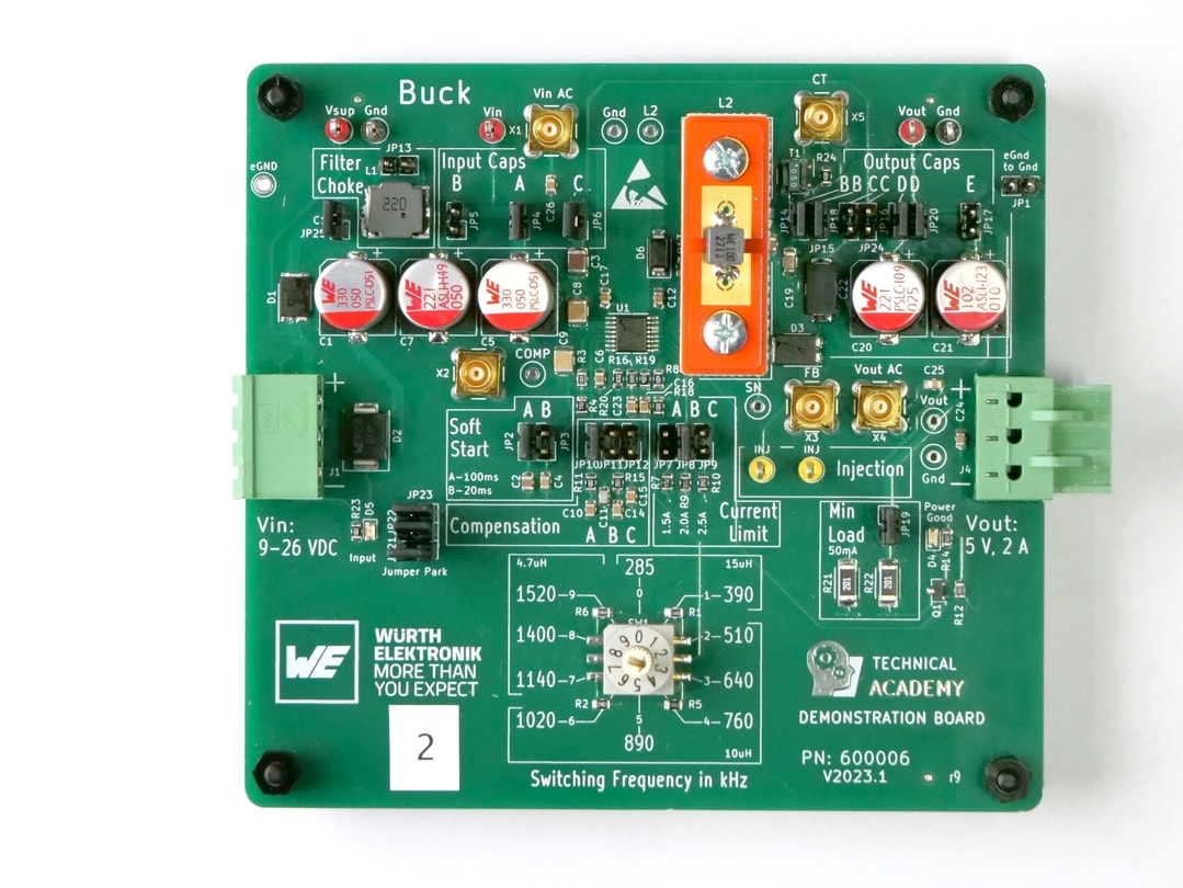
Buck converters are one of the simplest, cheapest and most common topologies. While this topology is not suited for applications where isolation is required, it is ideal as a DC to DC converter used to step- down voltages. Not only can you achieve high efficiency levels, but also high power levels using a buck converter, especially with poly-phase topologies. The down side to buck converters is that the input current is always discontinuous, resulting in higher EMI.
However, EMI issues can be addressed with filter components such as chip beads, common mode chokes and filter chokes.
The buck topology only requires a single inductor for single-phase applications, and catalog inductors for a wide range of applications are available. In addition, custom inductors can be developed for those special inductance versus current values that are required, as well as for applications requiring extra windings for sensing or supplying power to the controller.
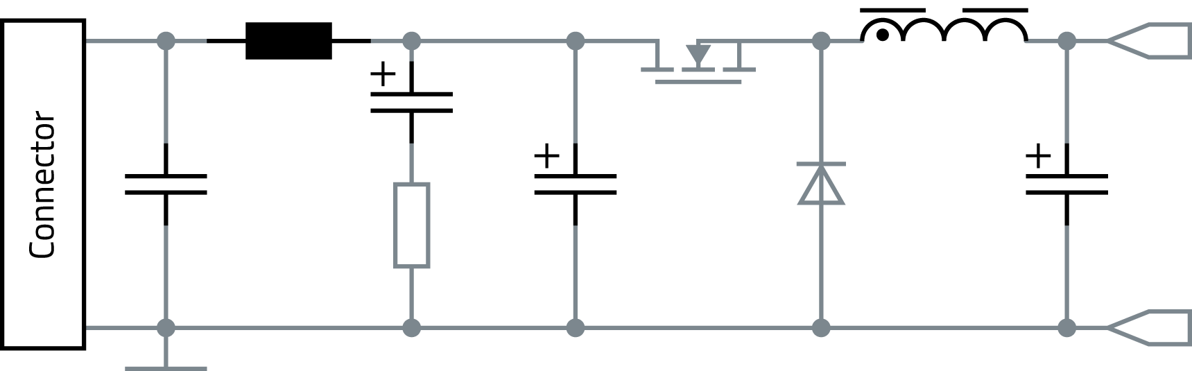
The boost topology, like the buck topology, is non-isolating. Unlike the buck topology, the boost steps up the voltage rather than stepping it down. Because the boost topology draws current in a continuous, even manner when operating in continuous conduction mode, it is an ideal choice for Power Factor Correction circuits. Like the buck topology, there are many catalog choices for the inductor used in boost circuits, and where there is a special need, custom inductors are available as well.
The buck-boost topology can either step the voltage up or down. This topology is particularly useful in battery powered applications, where the input voltage varies over time but has the disadvantage of inverting the output voltage. Another disadvantage to the buck-boost topology is that the switch does not have a ground, which complicates the drive circuit. Using only a single inductor like the buck and the boost topologies, the buck-boost inductor and EMI components are readily available.
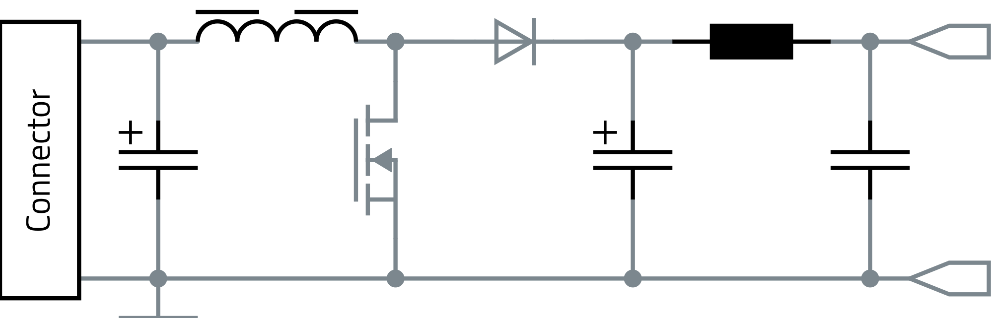
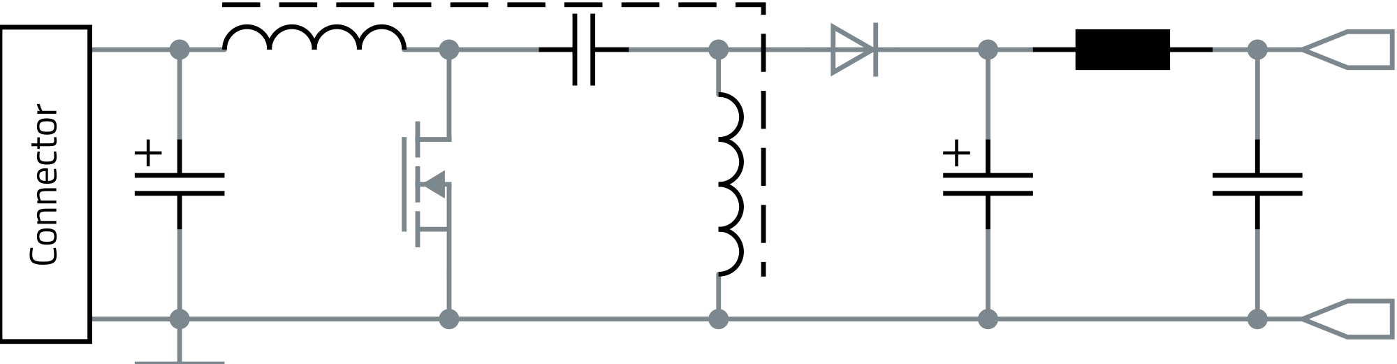
The SEPIC and Ćuk topologies both use capacitors for energy storage in addition to two inductors. The two inductors can be either separate inductors or a single component in the form of a coupled inductor. Both topologies are similar to the buck-boost topology in that they can step-up or step-down the input voltage, making them ideal for battery applications.
The SEPIC has the additional advantage over both the Ćuk and the buck-boost in that its output is non-inverting. An advantage to the SEPIC/ Ćuk topologies is that the capacitor can offer some limited isolation. Catalog coupled inductors are available for the SEPIC and Ćuk topologies, and custom inductors are readily available for special needs.
The flyback topology is essentially the buck-boost topology that is isolated by using a transformer as the storage inductor. But how does flyback converter work? The transformer not only provides isolation, but by varying the turns ratio, the output voltage can be adjusted. Since a transformer is used, multiple outputs are possible. The flyback is the simplest and most common of the isolated topologies for low-power applications. While they are well suited for high-output voltages, the peak currents are very high, and the topology does not lend itself well to output current above 10A.
One advantage of the flyback topology over the other isolated topologies is that many of them require a separate storage inductor. Since the flyback transformer is in reality the storage inductor, no separate inductor is needed. This, coupled with the fact that the rest of the circuitry is simple, makes the flyback topology a cost effective and popular topology.
Lean more about the flyback topology in the Application Guide
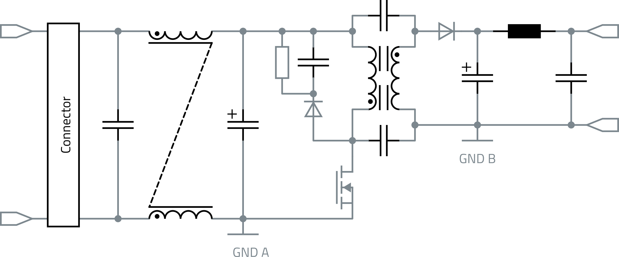
The forward converter is really just a transformer isolated buck converter. Like the flyback topology, the forward converter is best suited for lower power applications. While efficiency is comparable to the flyback, it does have the disadvantage of having an extra inductor on the output and is not well suited for high voltage outputs. The forward converter does have the advantage over the flyback converter when high output currents are required. Since the output current is non-pulsating, it is well suited for applications where the current is in excess of 15A.
Lean more about the forward topology in the Application Guide
The difference between flyback vs. forward converters lies in the inductive energy storage.
In the flyback converter, the energy storage is the transformer itself, which is why a transformer with an air gap is needed.
The forward converter uses a transformer without an air gap, so an additional storage choke is needed. The forward converter is therefore somewhat more complex in design, but also achieves a higher efficiency.
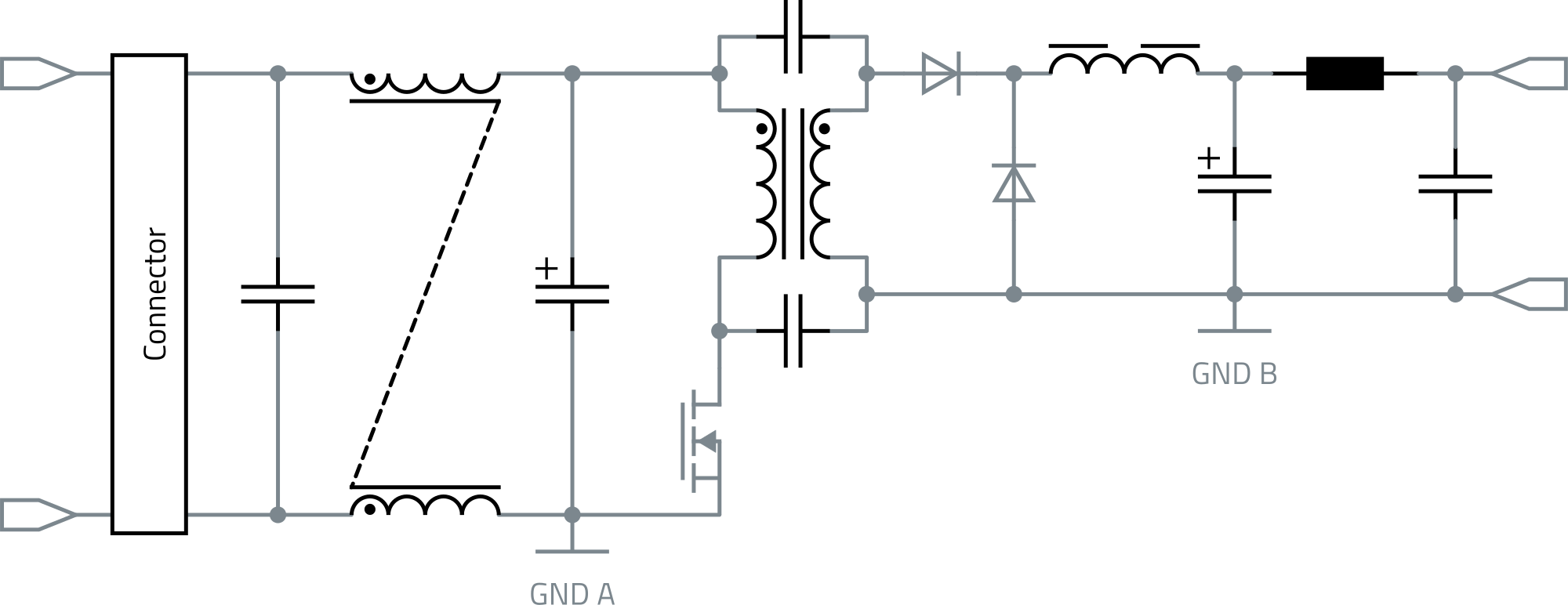
The push-pull topology is essentially a forward converter with two primary windings used to create a dual drive winding. This utilizes the core of the transformer much more efficiently than the flyback or the forward converters.
On the other hand, only half the copper is being used at a time, thereby increasing the copper losses significantly in a similar sized transformer. For similar power levels, the push-pull converter will have smaller filters compared to the forward converter.
However the advantage that push-pull converters have over flyback and forward converters is that they can be scaled up to higher powers. Switching control can be difficult with push-pull converters, because care has to be taken not to turn on both switches at the same time. Doing so will cause the equal and opposite flux in the transformer, resulting in a low impedance and a very large shoot-through current through the switch, potentially destroy- ing it.
The other disadvantage to the push-pull topology is that the switch stresses are very high (2∙VIN), which makes the topology undesirable for 250VAC and PFC applications.
Lean more about the push-pull topology in the Application Guide
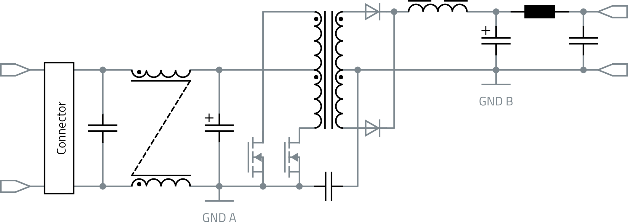
The half-bridge topology, like push-pull topologies, can be scaled up well to higher power levels and is based on the forward converter topology. This topology also has the same issue of the shoot-through current, if both switches are on at the same time. In order to control this, there needs to be a dead-time between the on-time of each switch. This limits the duty-cycle to about 45%. Beneficially, the half-bridge topology switching stresses are equal to the input voltage and make it much more suited to 250VAC and PFC applications.
On the flip side, the output cur- rents are much higher than the push-pull topology, thereby making it less suited for high current outputs.
The resonant LLC topology is a half-bridge topology that uses a resonant technique to reduce the switching losses due to zero voltage switching, even in no-load conditions. This topology scales up well to high power levels and has very low losses in devices that are on at all times. This topology is not as well suited for stand-by mode power supplies, as the resonant tank circuit needs to be energized continuously.
The resonant LLC also has the advantage over both push-pull and half-bridge topologies of being suitable for a wide range of input voltages. The down side to the resonant LLC topology is its complexity and cost.
Compare types of Switch Mode Power Supply Topologies, including Non-Isolated and Isolated Topologies here.