IC manufacturers (96)
- All manufacturers
 Analog Devices
 Infineon Technologies
 Maxim Integrated
 Microchip
 Onsemi
 Renesas
 ROHM
ROHM STMicroelectronics
 Texas Instruments
- 3peak incorporated (12)
- Ablic (23)
- Advanced Power (4)
- Allegro Microsystems (83)
- Alpha & Omega Semiconductor (37)
- AnalogySemi (3)
- AnDAPT Inc (130)
- Anpec (13)
- AXElite (2)
- Backward (6)
- Broadcom (47)
- Cambridge GaN Devices (16)
- Chipanalog Micro (10)
- Cologne Chips (1)
- Dialog Semiconductor (11)
- Diodes Incorporated (219)
- Divimath (8)
- Elmos AG (1)
- EPC (98)
- e-Peas Semiconductors (1)
- Eta Solutions Co. Ltd. (9)
- GaN Systems (6)
- Giantec (1)
- Gstek Wuxi (1)
- Helix Semiconductor (7)
- Ikanos (3)
- IKON (1)
- Indie Semiconductor (1)
- Innovision Semiconductor Inc (2)
- Intel (80)
- Inventchip Technology (3)
- ISSI (34)
- JoulWatt (20)
- KDPOF (2)
- Kinetic Technology (9)
- Lattice semiconductor Corporation (8)
- Littelfuse (1)
- M3 Technology (M3Tek) (4)
- Macnica (16)
- MaxLinear (175)
- MikroE (7)
- MindCet (1)
- Monolithic Power Systems (879)
- Navitas Semiconductor Inc (6)
- NewEdge Technologies, Inc. (1)
- Nexperia (2)
- Nisshinbo Micro Device Inc. (10)
- Nordic Semiconductor (1)
- Novosense Micro (1)
- NXP (312)
- O2 Micro International Ltd (10)
- On Bright (7)
- Panasonic (2)
- PN Junction Semiconductor (2)
- Power Integrations (96)
- Pulsiv (18)
- Qorvo (87)
- Realsil SuRealsil(tek) Microelectronics (1)
- Richtek (289)
- Sanken Electric Co., Ltd. (16)
- Sckipio (6)
- Semtech (90)
- SG-Micro (19)
- Silanna Semiconductor (8)
- Silergy Corporation (29)
- Silicon Laboratory Inc. (90)
- Silicontent Technology (56)
- Silvertel (54)
- Skyworks (31)
- Southchip (6)
- Summit Wireless (1)
- Tagore Tech (4)
- Taiwan Semiconductor (1)
- TDK Corporation (1)
- Tempo Semiconductor (1)
- Torex (37)
- Toshiba (25)
- Transphorm (21)
- TransSIP (2)
- Union (21)
- uPI Semiconductor (1)
- Valens Semiconductor (18)
- Wise Integration (1)
- Wolfspeed (5)
- Xilinx (18)
- XL Semiconductor (3)
- XYSemi (62)
Analog Devices LT3763 | Demoboard DC1831A
LT3763 Demo Board I High Power CC/CV Synchronous Buck LED Driver Controller
Overview
| Topology | Buck Converter |
| Input voltage | 12-60 V |
| Switching frequency | 380-480 kHz |
| Output 1 | 10 V / 10 A |
| IC revision | 2 |
Description
Demonstration circuit 1831A is a high power constant current, constant voltage synchronous buck controller featuring the LT®3763. The input of the demo board is up to 60V. The output is optimized for 10V, 10A as aLED driver. As an LED driver, the output current is being regulated until the output voltage reaches a programmed voltage limit. The voltage limit on the demo board is set to around 15V by R11 and R14. The load to be used with this demo board is high current LEDs or laser diodes. Smaller LEDs may not be able to handle the high current, even for a short period of time. It is necessary to mount the LED load on a proper heat sink. A fan may become necessary to avoid exceeding LED’s maximum temperature rating.
The input voltage range of the LT3763 itself is 6V to 60V. The demo board input range is 12V to 60V, therefore, the demo board utilizes 80V MOSFETs. If an application has a maximum input voltage of 48V, 60V MOSFETs such asBSC100N06LS3, can be used for better efficiency at lower voltage range. The typical efficiency of the demo board is 95% from a 24V input to a 10V, 10A load. The lower the input voltage, the higher the efficiency tends to be for a given load. At an output power level of 100W, even a one percentefficiency improvement is a big advantage in minimizing temperature rise. If an efficiency measurement is needed in an application, the output voltage must be measured at the output capacitors instead of at the LED load. Thisprevents cable loss from being counted as a loss of the board. The LT3763 turns off unnecessary circuits during PWM off period to minimize power losses. As a result, efficiency in many PWM dimming applications is high.
In most applications, input voltage reaching the maximum specification is a transient event. However, a fan helps the circuit to stay cool if running at or near peak input voltage at full load in steady state. If running in steady state at or near maximum input voltage and full load is required,please contact LTC applications engineering.
The demo circuit 1831A achieves fast current rise time from 0A to 10A. To see the real rise time, connecting wires between the LED and the board should be as short as possible to minimize the wire inductance and resistance.The cathode of the LED should return to LED– with R17 populated with a resistor in a few mΩ. It is recommended to measure the voltage on R17 with a short 50Ω coax cable directly into a BNC connector on the oscilloscope. The current can be calculated from the measured voltage. A current probe adds more delays to the rise time so using a current probe is not recommended. If fast rise time is not required, the cathode of the LED can be connected to GND as shown in Figure 2.
The LT3763 data sheet gives a complete description of the part, operation and application information. The data sheet must be read in conjunction with this quick start guide for demo circuit 1831A.
More information
Products
| Order Code | Datasheet | Simulation | Downloads | Product series | L (µH) | IRP,40K (A) | ISAT,10% (A) | ISAT,30% (A) | RDC (mΩ) | fres (MHz) | Material | Samples | |
|---|---|---|---|---|---|---|---|---|---|---|---|---|---|
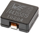 | 7443551280 | SPEC | 8 files | WE-HCI SMT Flat Wire High Current Inductor | 2.8 | 22.5 | 8 | 17.5 | 3.3 | 35 | WE-PERM |
| Order Code | Datasheet | Simulation | |
|---|---|---|---|
| 7443551280 | SPEC |
| Samples |
|---|
| Order Code | Datasheet | Simulation | Downloads | Product series | L (µH) | IRP,40K (A) | ISAT,10% (A) | ISAT,30% (A) | RDC (mΩ) | fres (MHz) | Material | Samples |
|---|