Power Integrations INN2124K | Demoboard DER-471
15 W Constant Voltage / Constant Current (CV / CC), Isolated Flyback Converter Using InnoSwitchTM-CE INN2124K
Details
| Topologie | Sperrwandler |
| Eingangsspannung | 85-265 V |
| Schaltfrequenz | 93 kHz |
| Ausgang 1 | 5 V / 3 A |
| IC-Revision | 1.3 |
Beschreibung
side.An inrush limiting thermistor (RT1) ensures that the inrush current is below the surgecurrent rating of the rectifier bridge BR1.Physically small bridge rectifier BR1 was selected due to the limited space in compactcharger designs.Inductor L1 and capacitor C10 filter high frequency common mode noise. Leakagereactance of the common mode choke L1 and X-capacitor C1 provide differential filteringto reduce conducted EMI which is in addition to the differential filtering provided by the π(pi) filter comprising of capacitors C2 and C3 and inductors L2 and L3.connected to the drain terminal of the integrated power MOSFET inside the InnoSwitch-CE IC (U1).A low cost RCD clamp formed by D1, R6, R7, R14 and C9 limits the peak drain voltagedue to the effects of transformer and output trace inductance.The IC is self-starting, using an internal high voltage current source to charge the BPPpin capacitor (C4) when AC is first applied. During normal operation the primary sideblock is powered from an auxiliary winding on the transformer. The output of this isconfigured as a flyback winding, rectified and filtered (D2 and C5) and fed in the BPP pinvia a current limiting resistor R4. A snubber comprising of resistor R5 and capacitor C6help to damp any high frequency ring across bias winding rectifier diode D2 and reducesradiated EMI.Output regulation is achieved using On/Off control, the number of enabled switchingcycles are adjusted based on the output load. At high load most switching cycles areenabled, and at light load or no-load most cycles are disabled or skipped. Once a cycle isenabled, the power MOSFET remain on until the primary current ramps to the devicecurrent limit for the specific operating state. There are four operating states (currentlimits) arrange such that the frequency content of the primary current switching patternremains out of the audible range until at light load where the transformer flux densityand therefore audible noise generation is at a very low level.
Eigenschaften
- InnoSwitch-CE - Industry first AC/DC ICs with isolated, safety rated integratedfeedback
- All the benefits of secondary side control with the simplicity of primary side regulation
- ±3% CV, ±5% CC regulation
- Insensitive to transformer variation
- Transient response independent of load timing
- Smaller, lower cost output capacitors
- <25 mW no-load input power at 230 VAC
- Built in line undervoltage and overvoltage protection
- Cable voltage drop compensation
- Built in synchronous rectification for high efficiency
Typische Anwendungen
- Adapter
Weiterführende Informationen
Artikeldaten
| Artikel Nr. | Datenblatt | Simulation | Downloads | Produktserie | Z @ 100 MHz (Ω) | Zmax (Ω) | Testbedingung Zmax | IR 2 (mA) | RDC max. (Ω) | Typ | Muster | |
|---|---|---|---|---|---|---|---|---|---|---|---|---|
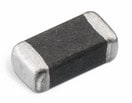
 | 742792122 | SPEC | 9 Dateien | WE-CBF SMT-Ferrit | 220 | 240 | 200 MHz | 3000 | 0.3 | High Speed |
| Muster |
|---|
| Artikel Nr. | Datenblatt | Simulation | Downloads | Produktserie | Z @ 100 MHz (Ω) | Zmax (Ω) | Testbedingung Zmax | IR 2 (mA) | RDC max. (Ω) | Typ | Muster |
|---|


