IC-Hersteller (96)
- Alle Hersteller
 Analog Devices
 Infineon Technologies
 Maxim Integrated
 Microchip
 Onsemi
 Renesas
 ROHM
ROHM STMicroelectronics
 Texas Instruments
- 3peak incorporated (12)
- Ablic (23)
- Advanced Power (4)
- Allegro Microsystems (83)
- Alpha & Omega Semiconductor (37)
- AnalogySemi (3)
- AnDAPT Inc (130)
- Anpec (13)
- AXElite (2)
- Backward (6)
- Broadcom (47)
- Cambridge GaN Devices (16)
- Chipanalog Micro (10)
- Cologne Chips (1)
- Dialog Semiconductor (11)
- Diodes Incorporated (219)
- Divimath (8)
- Elmos AG (1)
- EPC (98)
- e-Peas Semiconductors (1)
- Eta Solutions Co. Ltd. (9)
- GaN Systems (6)
- Giantec (1)
- Gstek Wuxi (1)
- Helix Semiconductor (7)
- Ikanos (3)
- IKON (1)
- Indie Semiconductor (1)
- Innovision Semiconductor Inc (2)
- Intel (80)
- Inventchip Technology (3)
- ISSI (34)
- JoulWatt (20)
- KDPOF (2)
- Kinetic Technology (9)
- Lattice semiconductor Corporation (8)
- Littelfuse (1)
- M3 Technology (M3Tek) (4)
- Macnica (16)
- MaxLinear (175)
- MikroE (7)
- MindCet (1)
- Monolithic Power Systems (879)
- Navitas Semiconductor Inc (6)
- NewEdge Technologies, Inc. (1)
- Nexperia (2)
- Nisshinbo Micro Device Inc. (10)
- Nordic Semiconductor (1)
- Novosense Micro (1)
- NXP (312)
- O2 Micro International Ltd (10)
- On Bright (7)
- Panasonic (2)
- PN Junction Semiconductor (2)
- Power Integrations (96)
- Pulsiv (18)
- Qorvo (87)
- Realsil SuRealsil(tek) Microelectronics (1)
- Richtek (289)
- Sanken Electric Co., Ltd. (16)
- Sckipio (6)
- Semtech (90)
- SG-Micro (19)
- Silanna Semiconductor (8)
- Silergy Corporation (29)
- Silicon Laboratory Inc. (90)
- Silicontent Technology (56)
- Silvertel (54)
- Skyworks (31)
- Southchip (6)
- Summit Wireless (1)
- Tagore Tech (4)
- Taiwan Semiconductor (1)
- TDK Corporation (1)
- Tempo Semiconductor (1)
- Torex (37)
- Toshiba (25)
- Transphorm (21)
- TransSIP (2)
- Union (21)
- uPI Semiconductor (1)
- Valens Semiconductor (18)
- Wise Integration (1)
- Wolfspeed (5)
- Xilinx (18)
- XL Semiconductor (3)
- XYSemi (62)
Details
| Topologie | Leistungsfaktor-Korrektur |
| Eingangsspannung | 160-264 V |
| Schaltfrequenz | 18-40 kHz |
| Ausgang 1 | 400 V |
| IC-Revision | 1.0 |
Beschreibung
The FAN9672 is an interleaved two-channel Continuous Conduction Mode (CCM) Power Factor Correction (PFC) controller IC intended for PFC pre-regulators. Incorporating circuits for leading edge, average current, and “boost”-type power factor correction; the FAN9672 enables the design of a power supply that fully complies with the IEC1000-3-2 specification. Interleaved operation provides substantial reduction in the input and output ripple currents and the conducted EMI filtering becomes simpler and cost effective.An innovative channel-management function allows the power level of the slave channels to be loaded and unloaded smoothly according to the setting voltage on the CM pin, improving the PFC converter’s load transient response.The FAN9672 also incorporates a variety of protection functions, including: peak current limiting, input voltage brownout protection, and TriFault Detect™ function
Eigenschaften
Continuous Conduction Mode ControlTwo-Channel PFC Control (Maximum)Average Current-Mode ControlPFC Slave Channel Management FunctionProgrammable Operation Frequency Range: 18 kHz~40 kHz or 55 kHz~75 kHzProgrammable PFC Output VoltageTwo Current-Limit FunctionsTriFault Detect™ Protects Against Feedback Loop FailureSAG ProtectionProgrammable Soft-StartUnder-Voltage Lockout (UVLO)Differential Current SensingAvailable in 32-Pin LQFP Package
Weiterführende Informationen
Artikeldaten
| Artikel Nr. | Datenblatt | Simulation | Downloads | Produktserie | λDom typ. (nm) | Farbe | λPeak typ. (nm) | IV typ. (mcd) | VF typ. (V) | Chiptechnologie | 2θ50% typ. (°) | C | Sicherheitsklasse | dV/dt (V/µs) | DF @ 1 kHz (%) | RISO | Betriebstemperatur | Raster (mm) | Tol. C | Bauform | Betriebstemperatur | DF (%) | Keramiktyp | Fl (mm) | ISAT (A) | fres (MHz) | Version | Endurance (h) | IRIPPLE (mA) | ILeak (µA) | Ø D (mm) | IR (A) | L (mH) | RDC max. (mΩ) | VR (V (AC)) | VT (V (AC)) | Material | L (mm) | W (mm) | H (mm) | Montageart | VRMS (V) | VDC (V) | VBR (V) | IPeak (A) | Wmax (J) | PDiss (mW) | Anwendung | VDE-Zulassung | Q (%) | IR 1 (mA) | Pins | Reihen | G (mm) | Gender | Typ | Verpackung | Farbe | Muster | |
|---|---|---|---|---|---|---|---|---|---|---|---|---|---|---|---|---|---|---|---|---|---|---|---|---|---|---|---|---|---|---|---|---|---|---|---|---|---|---|---|---|---|---|---|---|---|---|---|---|---|---|---|---|---|---|---|---|---|---|---|---|
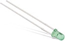 | 151051VS04000 | SPEC | 6 Dateien | WL-TMRC THT Mono-color Round Color | 572 | Hellgrün | 573 | 140 | 2.1 | AlInGaP | 40 | – | – | – | – | – | – | – | – | 5 mm | -40 °C up to +85 °C | – | – | – | – | – | – | – | – | – | – | – | – | – | – | – | – | 5 | 5 | 8.6 | THT | – | – | – | – | – | 75 | – | – | – | – | – | – | – | – | – | Lose | – | ||
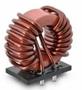 | 7448262510 | SPEC | 9 Dateien | WE-CMB Stromkompensierte Netzdrossel | – | – | – | – | – | – | – | – | – | – | – | – | -40 °C bis zu +125 °C | – | – | XXL | -40 °C up to +125 °C | – | – | – | – | – | THT | – | – | – | – | 25 | 1 | 4.5 | 250 | 1500 | MnZn | 44 | 23.5 | 43 | THT | – | – | – | – | – | – | – | 40042670 | – | – | 4 | – | 3 | – | – | – | – | ||
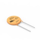 | 820423211 | SPEC | 6 Dateien | WE-VD Disk Varistor | – | – | – | – | – | – | – | – | – | – | – | – | -40 °C bis zu +85 °C | – | – | 20 mm | -40 °C up to +85 °C | – | – | – | – | – | THT | – | – | – | 23 | – | – | – | – | – | – | 23 | 5.3 | 27 | THT | 320 | 418 | 510 | 10000 | 382 | 1000 | – | Ja | – | – | – | – | – | – | – | – | – | ||
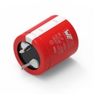
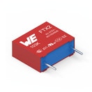 | 890324026027CS | SPEC | 8 Dateien | WCAP-FTX2 Folienkondensatoren | – | – | – | – | – | – | – | 1 µF | X2 | 170 | 0.1 | 10 GΩ | -40 °C bis zu +105 °C | 22.5 | ±10% | Pitch 22.5 mm | -40 °C up to +105 °C | – | – | – | – | – | – | – | – | – | – | – | – | – | 275 | – | – | 26 | 11 | 20 | Boxed THT | – | – | – | – | – | – | Across the mains | – | – | – | – | – | 4 | – | – | Karton | – | ||
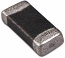 | 7447905 | SPEC | – | 6 Dateien | WE-MI SMT-Multilayer-Induktivitäten | – | – | – | – | – | – | – | – | – | – | – | – | – | – | – | 0805 | -55 °C up to +125 °C | – | – | – | – | 85 | – | – | – | – | – | 0.05 | 0.001 | 400 | – | – | – | 2 | 1.2 | 0.9 | SMT | – | – | – | – | – | – | – | – | 45 | 50 | – | – | – | – | – | – | – | |
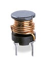 | 7447480151 | SPEC | 8 Dateien | WE-TI Tonneninduktivität | – | – | – | – | – | – | – | – | – | – | – | – | – | – | – | 1014 | -40 °C up to +125 °C | – | – | – | 2.1 | 3.5 | Standard | – | – | – | – | 2 | 0.15 | 180 | – | – | – | 10.5 | 10.5 | 14.5 | THT | – | – | – | – | – | – | – | – | – | – | – | – | – | – | – | – | – | ||
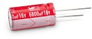 | 860020372004 | SPEC | 7 Dateien | WCAP-ATG5 Aluminium-Elektrolytkondensatoren | – | – | – | – | – | – | – | 47 µF | – | – | – | – | -40 °C bis zu +105 °C | 2 | ±20% | – | – | 15 | – | – | – | – | – | 2000 | 100 | 7.52 | 5 | – | – | – | 16 | – | – | 11 | – | – | – | – | – | – | – | – | – | – | – | – | – | – | – | – | – | – | Ammopack | – | ||
| 860020475015 | SPEC | 7 Dateien | WCAP-ATG5 Aluminium-Elektrolytkondensatoren | – | – | – | – | – | – | – | 560 µF | – | – | – | – | -40 °C bis zu +105 °C | 5 | ±20% | – | – | 14 | – | – | – | – | – | 2000 | 460 | 140 | 10 | – | – | – | 25 | – | – | 16 | – | – | – | – | – | – | – | – | – | – | – | – | – | – | – | – | – | – | Ammopack | – | ||
 | 861141486026 | SPEC | 7 Dateien | WCAP-AI3H Aluminium-Elektrolytkondensatoren | – | – | – | – | – | – | – | 680 µF | – | – | – | – | -25 °C bis zu +105 °C | 10 | ±20% | 35.0 x 55.0 | -25 °C up to +105 °C | 20 | – | – | – | – | – | 3000 | 2200 | 1659.52 | 35 | – | – | – | 450 | – | – | 57 | – | – | – | – | – | – | – | – | – | – | – | – | – | – | – | – | – | – | Tray | – | ||
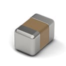 | 885012007051 | SPEC | 8 Dateien | WCAP-CSGP MLCCs 50 V(DC) | – | – | – | – | – | – | – | 10 pF | – | – | – | 10 GΩ | – | – | ±5% | 0805 | -55 °C up to +125 °C | – | NP0 Klasse I | 0.5 | – | – | – | – | – | – | – | – | – | – | 50 | – | – | 2 | 1.25 | 0.6 | – | – | – | – | – | – | – | – | – | 600 | – | – | – | – | – | – | 7" Tape & Reel | – | ||
| 885012007057 | SPEC | 8 Dateien | WCAP-CSGP MLCCs 50 V(DC) | – | – | – | – | – | – | – | 100 pF | – | – | – | 10 GΩ | – | – | ±5% | 0805 | -55 °C up to +125 °C | – | NP0 Klasse I | 0.5 | – | – | – | – | – | – | – | – | – | – | 50 | – | – | 2 | 1.25 | 0.6 | – | – | – | – | – | – | – | – | – | 1000 | – | – | – | – | – | – | 7" Tape & Reel | – | ||
| 885012207061 | SPEC | 8 Dateien | WCAP-CSGP MLCCs 25 V(DC) | – | – | – | – | – | – | – | 1.5 nF | – | – | – | 10 GΩ | – | – | ±10% | 0805 | -55 °C up to +125 °C | 3.5 | X7R Klasse II | 0.5 | – | – | – | – | – | – | – | – | – | – | 25 | – | – | 2 | 1.25 | 0.8 | – | – | – | – | – | – | – | – | – | – | – | – | – | – | – | – | 7" Tape & Reel | – | ||
| 885012207072 | SPEC | 8 Dateien | WCAP-CSGP MLCCs 25 V(DC) | – | – | – | – | – | – | – | 100 nF | – | – | – | 5 GΩ | – | – | ±10% | 0805 | -55 °C up to +125 °C | 3.5 | X7R Klasse II | 0.5 | – | – | – | – | – | – | – | – | – | – | 25 | – | – | 2 | 1.25 | 0.8 | – | – | – | – | – | – | – | – | – | – | – | – | – | – | – | – | 7" Tape & Reel | – | ||
| 885012207074 | SPEC | 7 Dateien | WCAP-CSGP MLCCs 25 V(DC) | – | – | – | – | – | – | – | 220 nF | – | – | – | 2.3 GΩ | – | – | ±10% | 0805 | -55 °C up to +125 °C | 3.5 | X7R Klasse II | 0.5 | – | – | – | – | – | – | – | – | – | – | 25 | – | – | 2 | 1.25 | 1.25 | – | – | – | – | – | – | – | – | – | – | – | – | – | – | – | – | 7" Tape & Reel | – | ||
| 885012207076 | SPEC | 7 Dateien | WCAP-CSGP MLCCs 25 V(DC) | – | – | – | – | – | – | – | 470 nF | – | – | – | 1.1 GΩ | – | – | ±10% | 0805 | -55 °C up to +125 °C | 3.5 | X7R Klasse II | 0.5 | – | – | – | – | – | – | – | – | – | – | 25 | – | – | 2 | 1.25 | 1.25 | – | – | – | – | – | – | – | – | – | – | – | – | – | – | – | – | 7" Tape & Reel | – | ||
| 885012207078 | SPEC | 7 Dateien | WCAP-CSGP MLCCs 25 V(DC) | – | – | – | – | – | – | – | 1 µF | – | – | – | 0.5 GΩ | – | – | ±10% | 0805 | -55 °C up to +125 °C | 5 | X7R Klasse II | 0.5 | – | – | – | – | – | – | – | – | – | – | 25 | – | – | 2 | 1.25 | 1.25 | – | – | – | – | – | – | – | – | – | – | – | – | – | – | – | – | 7" Tape & Reel | – | ||
| 885012207084 | SPEC | 8 Dateien | WCAP-CSGP MLCCs 50 V(DC) | – | – | – | – | – | – | – | 470 pF | – | – | – | 10 GΩ | – | – | ±10% | 0805 | -55 °C up to +125 °C | 2.5 | X7R Klasse II | 0.5 | – | – | – | – | – | – | – | – | – | – | 50 | – | – | 2 | 1.25 | 0.8 | – | – | – | – | – | – | – | – | – | – | – | – | – | – | – | – | 7" Tape & Reel | – | ||
| 885012207086 | SPEC | 8 Dateien | WCAP-CSGP MLCCs 50 V(DC) | – | – | – | – | – | – | – | 1 nF | – | – | – | 10 GΩ | – | – | ±10% | 0805 | -55 °C up to +125 °C | 2.5 | X7R Klasse II | 0.5 | – | – | – | – | – | – | – | – | – | – | 50 | – | – | 2 | 1.25 | 0.8 | – | – | – | – | – | – | – | – | – | – | – | – | – | – | – | – | 7" Tape & Reel | – | ||
| 885012207088 | SPEC | 8 Dateien | WCAP-CSGP MLCCs 50 V(DC) | – | – | – | – | – | – | – | 2.2 nF | – | – | – | 10 GΩ | – | – | ±10% | 0805 | -55 °C up to +125 °C | 2.5 | X7R Klasse II | 0.5 | – | – | – | – | – | – | – | – | – | – | 50 | – | – | 2 | 1.25 | 0.8 | – | – | – | – | – | – | – | – | – | – | – | – | – | – | – | – | 7" Tape & Reel | – | ||
| 885012207092 | SPEC | 8 Dateien | WCAP-CSGP MLCCs 50 V(DC) | – | – | – | – | – | – | – | 10 nF | – | – | – | 10 GΩ | – | – | ±10% | 0805 | -55 °C up to +125 °C | 2.5 | X7R Klasse II | 0.5 | – | – | – | – | – | – | – | – | – | – | 50 | – | – | 2 | 1.25 | 0.8 | – | – | – | – | – | – | – | – | – | – | – | – | – | – | – | – | 7" Tape & Reel | – | ||
| 885012207094 | SPEC | 8 Dateien | WCAP-CSGP MLCCs 50 V(DC) | – | – | – | – | – | – | – | 22 nF | – | – | – | 10 GΩ | – | – | ±10% | 0805 | -55 °C up to +125 °C | 2.5 | X7R Klasse II | 0.5 | – | – | – | – | – | – | – | – | – | – | 50 | – | – | 2 | 1.25 | 0.8 | – | – | – | – | – | – | – | – | – | – | – | – | – | – | – | – | 7" Tape & Reel | – | ||
| 885012207096 | SPEC | 8 Dateien | WCAP-CSGP MLCCs 50 V(DC) | – | – | – | – | – | – | – | 47 nF | – | – | – | 10 GΩ | – | – | ±10% | 0805 | -55 °C up to +125 °C | 2.5 | X7R Klasse II | 0.5 | – | – | – | – | – | – | – | – | – | – | 50 | – | – | 2 | 1.25 | 0.8 | – | – | – | – | – | – | – | – | – | – | – | – | – | – | – | – | 7" Tape & Reel | – | ||
| 885012208069 | SPEC | 8 Dateien | WCAP-CSGP MLCCs 25 V(DC) | – | – | – | – | – | – | – | 10 µF | – | – | – | 0.01 GΩ | – | – | ±10% | 1206 | -55 °C up to +125 °C | 10 | X7R Klasse II | 0.5 | – | – | – | – | – | – | – | – | – | – | 25 | – | – | 3.2 | 1.6 | 1.6 | – | – | – | – | – | – | – | – | – | – | – | – | – | – | – | – | 7" Tape & Reel | – | ||
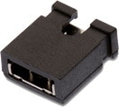 | 60900213421 | SPEC | – | 3 Dateien | WR-PHD 2.54 mm Multi-Jumper Jumper with Test Point | – | – | – | – | – | – | – | – | – | – | – | 1000 MΩ | – | 2.54 | – | – | -40 °C up to +125 °C | – | – | – | – | – | – | – | – | – | – | 3 | – | – | – | – | – | 2.44 | – | – | – | – | – | – | – | – | – | – | – | – | – | 1 | – | – | Jumper | – | Beutel | Schwarz | |
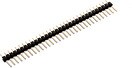 | 61300211121 | SPEC | – | 6 Dateien | WR-PHD 2.54 mm THT Pin Header | – | – | – | – | – | – | – | – | – | – | – | 1000 MΩ | – | 2.54 | – | – | -40 °C up to +105 °C | – | – | – | – | – | – | – | – | – | – | 3 | – | – | – | – | – | 5.08 | – | – | THT | – | – | – | – | – | – | – | – | – | – | 2 | Single | – | Pin Header | Gerade | Beutel | – | |
| 750342844 | SPEC | – | – | Power Inductor | – | – | – | – | – | – | – | – | – | – | – | – | – | – | – | – | – | – | – | – | – | – | – | – | – | – | – | – | – | – | – | – | – | – | – | – | – | – | – | – | – | – | – | – | – | – | – | – | – | – | – | – | – | – | ||
| 750342940 | SPEC | – | – | PFC Inductor | – | – | – | – | – | – | – | – | – | – | – | – | – | – | – | – | – | – | – | – | – | – | – | – | – | – | – | – | – | – | – | – | – | – | – | – | – | – | – | – | – | – | – | – | – | – | – | – | – | – | – | – | – | – |
| Muster |
|---|
| Artikel Nr. | Datenblatt | Simulation | Downloads | Produktserie | λDom typ. (nm) | Farbe | λPeak typ. (nm) | IV typ. (mcd) | VF typ. (V) | Chiptechnologie | 2θ50% typ. (°) | C | Sicherheitsklasse | dV/dt (V/µs) | DF @ 1 kHz (%) | RISO | Betriebstemperatur | Raster (mm) | Tol. C | Bauform | Betriebstemperatur | DF (%) | Keramiktyp | Fl (mm) | ISAT (A) | fres (MHz) | Version | Endurance (h) | IRIPPLE (mA) | ILeak (µA) | Ø D (mm) | IR (A) | L (mH) | RDC max. (mΩ) | VR (V (AC)) | VT (V (AC)) | Material | L (mm) | W (mm) | H (mm) | Montageart | VRMS (V) | VDC (V) | VBR (V) | IPeak (A) | Wmax (J) | PDiss (mW) | Anwendung | VDE-Zulassung | Q (%) | IR 1 (mA) | Pins | Reihen | G (mm) | Gender | Typ | Verpackung | Farbe | Muster |
|---|