IC-Hersteller (96)
- Alle Hersteller
 Analog Devices
 Infineon Technologies
 Maxim Integrated
 Microchip
 Onsemi
 Renesas
 ROHM
ROHM STMicroelectronics
 Texas Instruments
- 3peak incorporated (12)
- Ablic (23)
- Advanced Power (4)
- Allegro Microsystems (83)
- Alpha & Omega Semiconductor (37)
- AnalogySemi (3)
- AnDAPT Inc (130)
- Anpec (13)
- AXElite (2)
- Backward (6)
- Broadcom (47)
- Cambridge GaN Devices (16)
- Chipanalog Micro (10)
- Cologne Chips (1)
- Dialog Semiconductor (11)
- Diodes Incorporated (219)
- Divimath (8)
- Elmos AG (1)
- EPC (98)
- e-Peas Semiconductors (1)
- Eta Solutions Co. Ltd. (9)
- GaN Systems (6)
- Giantec (1)
- Gstek Wuxi (1)
- Helix Semiconductor (7)
- Ikanos (3)
- IKON (1)
- Indie Semiconductor (1)
- Innovision Semiconductor Inc (2)
- Intel (80)
- Inventchip Technology (3)
- ISSI (34)
- JoulWatt (20)
- KDPOF (2)
- Kinetic Technology (9)
- Lattice semiconductor Corporation (8)
- Littelfuse (1)
- M3 Technology (M3Tek) (4)
- Macnica (16)
- MaxLinear (175)
- MikroE (7)
- MindCet (1)
- Monolithic Power Systems (879)
- Navitas Semiconductor Inc (6)
- NewEdge Technologies, Inc. (1)
- Nexperia (2)
- Nisshinbo Micro Device Inc. (10)
- Nordic Semiconductor (1)
- Novosense Micro (1)
- NXP (312)
- O2 Micro International Ltd (10)
- On Bright (7)
- Panasonic (2)
- PN Junction Semiconductor (2)
- Power Integrations (96)
- Pulsiv (18)
- Qorvo (87)
- Realsil SuRealsil(tek) Microelectronics (1)
- Richtek (289)
- Sanken Electric Co., Ltd. (16)
- Sckipio (6)
- Semtech (90)
- SG-Micro (19)
- Silanna Semiconductor (8)
- Silergy Corporation (29)
- Silicon Laboratory Inc. (90)
- Silicontent Technology (56)
- Silvertel (54)
- Skyworks (31)
- Southchip (6)
- Summit Wireless (1)
- Tagore Tech (4)
- Taiwan Semiconductor (1)
- TDK Corporation (1)
- Tempo Semiconductor (1)
- Torex (37)
- Toshiba (25)
- Transphorm (21)
- TransSIP (2)
- Union (21)
- uPI Semiconductor (1)
- Valens Semiconductor (18)
- Wise Integration (1)
- Wolfspeed (5)
- Xilinx (18)
- XL Semiconductor (3)
- XYSemi (62)
Details
| Topologie | Sonstige Topologie |
| IC-Revision | 1A |
Beschreibung
A well laid out PCB does not radiate much EMI all by itself from the current carrying traces. In order to get EMI compliancea PCB should have:■■ Ideally six layer PCB with two full ground planes. Four layer PCBs are okay.■■Make sure there is sufficient vias between the ground planes.■■Make sure to minimize the switching current loops on the board.■■Current carrying traces must be kept as short as possible and running on a layer close to the ground plane.■■ Power ground plane and the signal ground must be connected at only one point.Most of the radiation takes place when we connect leads to the power source and the electronic load. These leads areusually about 0.5m to 1.5m and they act as a very good antenna for frequencies between 30MHz to 1GHz.Figure 1 depicts a typical test setup in anechoic EMI test chamber. The high frequency power switching generates widespectrum noise because of all the parasitic inductances and capacitances ringing at different frequencies and with differentdamping factor at different times of the switching period.
Weiterführende Informationen
Artikeldaten
| Artikel Nr. | Datenblatt | Simulation | Downloads | Produktserie | Z @ 100 MHz (Ω) | Zmax (Ω) | Testbedingung Zmax | IR (mA) | Z @ 1 GHz (Ω) | H (mm) | Typ | Muster | |
|---|---|---|---|---|---|---|---|---|---|---|---|---|---|
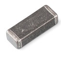 | 74279226101 | SPEC | 8 Dateien | WE-MPSB EMI Multilayer Power Suppression Bead | 100 | 160 | 1100 MHz | 8000 | 150 | 2.3 | High Current |
| Artikel Nr. | Datenblatt | Simulation | |
|---|---|---|---|
| 74279226101 | SPEC |
| Muster |
|---|
| Artikel Nr. | Datenblatt | Simulation | Downloads | Produktserie | Z @ 100 MHz (Ω) | Zmax (Ω) | Testbedingung Zmax | IR (mA) | Z @ 1 GHz (Ω) | H (mm) | Typ | Muster |
|---|