IC-Hersteller (96)
- Alle Hersteller
 Analog Devices
 Infineon Technologies
 Maxim Integrated
 Microchip
 Onsemi
 Renesas
 ROHM
ROHM STMicroelectronics
 Texas Instruments
- 3peak incorporated (12)
- Ablic (23)
- Advanced Power (4)
- Allegro Microsystems (83)
- Alpha & Omega Semiconductor (37)
- AnalogySemi (3)
- AnDAPT Inc (130)
- Anpec (13)
- AXElite (2)
- Backward (6)
- Broadcom (47)
- Cambridge GaN Devices (16)
- Chipanalog Micro (10)
- Cologne Chips (1)
- Dialog Semiconductor (11)
- Diodes Incorporated (219)
- Divimath (8)
- Elmos AG (1)
- EPC (98)
- e-Peas Semiconductors (1)
- Eta Solutions Co. Ltd. (9)
- GaN Systems (6)
- Giantec (1)
- Gstek Wuxi (1)
- Helix Semiconductor (7)
- Ikanos (3)
- IKON (1)
- Indie Semiconductor (1)
- Innovision Semiconductor Inc (2)
- Intel (80)
- Inventchip Technology (3)
- ISSI (34)
- JoulWatt (20)
- KDPOF (2)
- Kinetic Technology (9)
- Lattice semiconductor Corporation (8)
- Littelfuse (1)
- M3 Technology (M3Tek) (4)
- Macnica (16)
- MaxLinear (175)
- MikroE (7)
- MindCet (1)
- Monolithic Power Systems (879)
- Navitas Semiconductor Inc (6)
- NewEdge Technologies, Inc. (1)
- Nexperia (2)
- Nisshinbo Micro Device Inc. (10)
- Nordic Semiconductor (1)
- Novosense Micro (1)
- NXP (312)
- O2 Micro International Ltd (10)
- On Bright (7)
- Panasonic (2)
- PN Junction Semiconductor (2)
- Power Integrations (96)
- Pulsiv (18)
- Qorvo (87)
- Realsil SuRealsil(tek) Microelectronics (1)
- Richtek (289)
- Sanken Electric Co., Ltd. (16)
- Sckipio (6)
- Semtech (90)
- SG-Micro (19)
- Silanna Semiconductor (8)
- Silergy Corporation (29)
- Silicon Laboratory Inc. (90)
- Silicontent Technology (56)
- Silvertel (54)
- Skyworks (31)
- Southchip (6)
- Summit Wireless (1)
- Tagore Tech (4)
- Taiwan Semiconductor (1)
- TDK Corporation (1)
- Tempo Semiconductor (1)
- Torex (37)
- Toshiba (25)
- Transphorm (21)
- TransSIP (2)
- Union (21)
- uPI Semiconductor (1)
- Valens Semiconductor (18)
- Wise Integration (1)
- Wolfspeed (5)
- Xilinx (18)
- XL Semiconductor (3)
- XYSemi (62)
Infineon Technologies IRS2007S | Demoboard EVAL-PS-IRS200x-OM30118SB
IRS2005S/IRS2007S/IRS2008S drive board for stepper motor
Details
| Topologie | Sonstige Topologie |
| Eingangsspannung | 24-72 V |
| Ausgang 1 | 3 A |
| IC-Revision | 1.0 |
Beschreibung
The power stage of the evaluation board EVAL-PS-IRS200x-OM30118SB consists of four phases with individual leg shunt, which is a popular topology for stepper motor driving. The input voltage 24~72 VDC is available for most of the stepper motors on the market. The MOSFETs are selected with IPP180N10N3 G (100 V/18 mΩ), and driven by the 200 V series PNJ gate drivers IRS2005S/IRS2007S/IRS2008S accordingly. Each phase leg current is sensed by the leg shunt, and exported to the control interface in differential mode. The board can run a stepper motor by connecting to an external controller. The board is originally soldered with the IRS2005S (positive logic inputs), and can be replaced by two other parts with the same footprint for different logic inputs (refer to Table 5). The board is available via regular Infineon distribution partners as well as on Infineon's website. The features of this board are described in Chapter 3 of this document. The remaining sections provide information to enable customers to copy, modify and qualify the design for production according to their own specific requirements. Environmental conditions were considered in the design of the EVAL-PS-IRS200x-OM30118SB. However, the board has not been qualified in terms of safety requirements, manufacturing and operation over the entire operating temperature range or lifetime. The boards provided by Infineon are subject to functional testing only. Figure 1 depicts the block diagram of the EVAL-PS-IRS200x-OM30118SB. The shaded parts are those contained in the PCB. The auxiliary power supply VCC has to come from the external input.
Eigenschaften
- I O+ / I O- of 290 mA / 600 mA typical gate current
- Gate drive supplies up to 20 V per channel
- Under voltage lockout for V CC, V BS
- 3.3 V, 5 V, 15 V input logic compatible
- Tolerant to negative transient voltage
- Designed for use with bootstrap power supplies
- Cross-conduction prevention logic
- Matched propagation delay for both channels
- Internal set dead-time
- High-side output in phase with HIN input
- Low-side output out of phase wit LIN input
- -40°C to 125°C operating range
- 2 kV HBM ESD
- RoHS compliant
Weiterführende Informationen
Artikeldaten
| Artikel Nr. | Datenblatt | Simulation | Downloads | Produktserie | Anwendung | PCB/Kabel/Panel | Modularity | Wire Section | λDom typ. (nm) | Farbe | λPeak typ. (nm) | IV typ. (mcd) | VF typ. (V) | Chiptechnologie | 2θ50% typ. (°) | C | VR (V (DC)) | dV/dt (V/µs) | DF @ 1 kHz (%) | RISO | Betriebstemperatur | Raster (mm) | L (mm) | W (mm) | Pins | Reihen | H (mm) | G (mm) | Gender | Typ | IR (A) | Verpackung | Muster | |
|---|---|---|---|---|---|---|---|---|---|---|---|---|---|---|---|---|---|---|---|---|---|---|---|---|---|---|---|---|---|---|---|---|---|---|
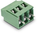 | 691236510003 | SPEC | – | 6 Dateien | WR-TBL Serie 2365 - 5.08 mm Horiz. Entry w. Rising Cage Clamp | Rising Cage Clamp | PCB | Ja | 12 to 30 (AWG) 3.31 to 0.0509 (mm²) | – | – | – | – | – | – | – | – | – | – | – | – | -30 °C bis zu +120 °C | 5.08 | 15.24 | – | 3 | – | – | – | – | Horizontal Cable Entry | 20 | Karton | |
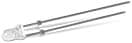 | 151033GS03000 | SPEC | – | 7 Dateien | WL-TMRW THT Mono-color Round Waterclear | – | – | – | – | 530 | Grün | 525 | 15000 | 3.2 | InGaN | 30 | – | – | – | – | – | – | – | 3 | 3 | – | – | 5.3 | – | – | – | – | Lose | |
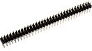 | 61302021121 | SPEC | – | 6 Dateien | WR-PHD 2.54 mm THT Dual Pin Header | – | – | – | – | – | – | – | – | – | – | – | – | – | – | – | 1000 MΩ | – | 2.54 | 25.4 | – | 20 | Dual | – | – | Pin Header | Gerade | 3 | Beutel | |
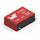 | 890263425004CS | SPEC | 8 Dateien | WCAP-FTBE Folienkondensatoren | – | – | – | – | – | – | – | – | – | – | – | 2.2 µF | 100 | 9 | 1 | 3000 Ω*F | -40 °C bis zu +85 °C | 15 | 18 | 8.5 | – | – | 15 | 4 | – | – | – | Karton |
| Artikel Nr. | Datenblatt | Simulation | |
|---|---|---|---|
| 691236510003 | SPEC | – |
| 151033GS03000 | SPEC | – |
| 61302021121 | SPEC | – |
| 890263425004CS | SPEC |
| Muster |
|---|
| Artikel Nr. | Datenblatt | Simulation | Downloads | Produktserie | Anwendung | PCB/Kabel/Panel | Modularity | Wire Section | λDom typ. (nm) | Farbe | λPeak typ. (nm) | IV typ. (mcd) | VF typ. (V) | Chiptechnologie | 2θ50% typ. (°) | C | VR (V (DC)) | dV/dt (V/µs) | DF @ 1 kHz (%) | RISO | Betriebstemperatur | Raster (mm) | L (mm) | W (mm) | Pins | Reihen | H (mm) | G (mm) | Gender | Typ | IR (A) | Verpackung | Muster |
|---|