IC-Hersteller Diodes Incorporated
IC-Hersteller (96)
- Alle Hersteller
 Analog Devices
 Infineon Technologies
 Maxim Integrated
 Microchip
 Onsemi
 Renesas
 ROHM
ROHM STMicroelectronics
 Texas Instruments
- 3peak incorporated (12)
- Ablic (23)
- Advanced Power (4)
- Allegro Microsystems (83)
- Alpha & Omega Semiconductor (37)
- AnalogySemi (3)
- AnDAPT Inc (130)
- Anpec (13)
- AXElite (2)
- Backward (6)
- Broadcom (47)
- Cambridge GaN Devices (16)
- Chipanalog Micro (10)
- Cologne Chips (1)
- Dialog Semiconductor (11)
- Diodes Incorporated (217)
- Divimath (8)
- Elmos AG (1)
- EPC (98)
- e-Peas Semiconductors (1)
- Eta Solutions Co. Ltd. (9)
- GaN Systems (6)
- Giantec (1)
- Gstek Wuxi (1)
- Helix Semiconductor (7)
- Ikanos (3)
- IKON (1)
- Indie Semiconductor (1)
- Innovision Semiconductor Inc (2)
- Intel (80)
- Inventchip Technology (3)
- ISSI (34)
- JoulWatt (20)
- KDPOF (2)
- Kinetic Technology (9)
- Lattice semiconductor Corporation (8)
- Littelfuse (1)
- M3 Technology (M3Tek) (4)
- Macnica (16)
- MaxLinear (175)
- MikroE (7)
- MindCet (1)
- Monolithic Power Systems (879)
- Navitas Semiconductor Inc (6)
- NewEdge Technologies, Inc. (1)
- Nexperia (2)
- Nisshinbo Micro Device Inc. (10)
- Nordic Semiconductor (1)
- Novosense Micro (1)
- NXP (312)
- O2 Micro International Ltd (10)
- On Bright (7)
- Panasonic (2)
- PN Junction Semiconductor (2)
- Power Integrations (96)
- Pulsiv (18)
- Qorvo (86)
- Realsil SuRealsil(tek) Microelectronics (1)
- Richtek (289)
- Sanken Electric Co., Ltd. (16)
- Sckipio (6)
- Semtech (90)
- SG-Micro (19)
- Silanna Semiconductor (8)
- Silergy Corporation (29)
- Silicon Laboratory Inc. (90)
- Silicontent Technology (56)
- Silvertel (54)
- Skyworks (31)
- Southchip (6)
- Summit Wireless (1)
- Tagore Tech (4)
- Taiwan Semiconductor (1)
- TDK Corporation (1)
- Tempo Semiconductor (1)
- Torex (37)
- Toshiba (25)
- Transphorm (21)
- TransSIP (2)
- Union (21)
- uPI Semiconductor (1)
- Valens Semiconductor (18)
- Wise Integration (1)
- Wolfspeed (5)
- Xilinx (18)
- XL Semiconductor (3)
- XYSemi (62)
Details
| Topologie | Sperrwandler |
| Eingangsspannung | 90-265 V |
| Schaltfrequenz | 20-120 kHz |
| Ausgang 1 | 12 V / 3.5 A |
| IC-Revision | 1 |
Beschreibung
The AP3301 EV1 board is a Quasi-Resonant Flyback converter, operating under CCM and DCM, the valley switching on mode function will be appeared at all DCM region of variable load & high input AC line voltage conditions, it is employed with the peak-current control & multi-mode PWM control functions. Based on above the high performances are optimized & achieved. It is designed to serve as an example for High Efficiency, cost-effective & components less consumer home appliance systems. Its output power is rated at 42W with 12V-3.5A and peak power can be reach to 48W at peak time. Its input power consumption is less than 100mW at no load and meets DOE VI and CoC Tier 2 energy efficiency requirement.
Eigenschaften
- Very Low Start-up Current
- Multi-Mode Control
- Quasi-Resonant Operation with Valley Lock
- Fixed Frequency CCM Operation at Low Line Heavy Load
- Non-Audible-Noise Quasi-Resonant Control
- Internal Slope Compensation
- Soft Start During Startup Process
- Frequency Fold Back for High Average Efficiency
- Secondary Winding Short Protection with FOCP
- Frequency dithering for Reducing EMI
- VCC Maintain Mode
- Useful Pin Fault Protection: SENSE Pin Floating, FB/Opto-coupler Open/Short
- Comprehensive System Protection Feature: VCC Over Voltage Protection (VOVP), Over Load Protection (OLP)
- Brown Out Protection (BNO)
- Secondary Side OVP (SOVP)
- Mini Size Package of SOT26
- Totally Lead-free & Fully RoHS Compliant
- Halogen and Antimony Free. “Green” Device
Typische Anwendungen
- Power home Appliances systems / Set-top box & TV power supply
- Switching AC-DC Adaptor & Charger / Open frame switching power supply
Weiterführende Informationen
Artikeldaten
| Artikel Nr. | Datenblatt | Simulation | Downloads | Produktserie | Anwendung | C | Sicherheitsklasse | dV/dt (V/µs) | DF @ 1 kHz (%) | RISO | Betriebstemperatur | Raster (mm) | Verpackung | Tol. C | Bauform | Betriebstemperatur | Q (%) | DF (%) | Keramiktyp | Fl (mm) | Endurance (h) | IRIPPLE (mA) | ILeak (µA) | Ø D (mm) | IR (A) | L (mH) | RDC max. (mΩ) | VR (V (AC)) | VT (V (AC)) | Material | L (mm) | W (mm) | H (mm) | Montageart | Muster | |
|---|---|---|---|---|---|---|---|---|---|---|---|---|---|---|---|---|---|---|---|---|---|---|---|---|---|---|---|---|---|---|---|---|---|---|---|---|
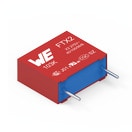 | 890324024002 | SPEC | 8 Dateien | WCAP-FTX2 Folienkondensatoren | Across the mains | 220 nF | X2 | 240 | 0.1 | 30 GΩ | -40 °C bis zu +105 °C | 12.5 | Lose | ±10% | Pitch 12.5 mm | -40 °C up to +105 °C | – | – | – | – | – | – | – | – | – | – | – | 275 | – | – | 15 | 7 | 12.5 | Boxed THT | ||
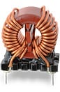 | 744822110 | SPEC | 10 Dateien | WE-CMB Stromkompensierte Netzdrossel | – | – | – | – | – | – | -40 °C bis zu +125 °C | – | – | – | Typ S | -40 °C up to +125 °C | – | – | – | – | – | – | – | – | 1 | 10 | 360 | 250 | 1500 | MnZn | 17.5 | 13 | 22 | THT | ||
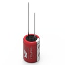
 | 860020572002 | SPEC | 7 Dateien | WCAP-ATG5 Aluminium-Elektrolytkondensatoren | – | 6.8 µF | – | – | – | – | -40 °C bis zu +105 °C | 2 | Ammopack | ±20% | – | – | – | 12 | – | – | 2000 | 36 | 3 | 5 | – | – | – | 35 | – | – | 11 | – | – | – | ||
| 860021381021 | SPEC | 7 Dateien | WCAP-ATG5 Aluminium-Elektrolytkondensatoren | – | 120 µF | – | – | – | – | -25 °C bis zu +105 °C | 7.5 | Ammopack | ±20% | – | – | – | 15 | – | – | 2000 | 550 | 1440 | 18 | – | – | – | 400 | – | – | 31.5 | – | – | – | ||
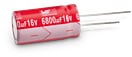
 | 870025375009 | SPEC | 7 Dateien | WCAP-PTG5 Aluminium-Polymer-Kondensatoren | – | 680 µF | – | – | – | – | -55 °C bis zu +105 °C | 5 | Ammopack | ±20% | – | – | – | 10 | – | – | 2000 | 5500 | 1000 | 10 | – | – | – | 16 | – | – | 12.5 | – | – | Radial THT | ||
 | 885012007057 | SPEC | 8 Dateien | WCAP-CSGP MLCCs 50 V(DC) | – | 100 pF | – | – | – | 10 GΩ | – | – | 7" Tape & Reel | ±5% | 0805 | -55 °C up to +125 °C | 1000 | – | NP0 Klasse I | 0.5 | – | – | – | – | – | – | – | 50 | – | – | 2 | 1.25 | 0.6 | – | ||
| 885012007061 | SPEC | 8 Dateien | WCAP-CSGP MLCCs 50 V(DC) | – | 470 pF | – | – | – | 10 GΩ | – | – | 7" Tape & Reel | ±5% | 0805 | -55 °C up to +125 °C | 1000 | – | NP0 Klasse I | 0.5 | – | – | – | – | – | – | – | 50 | – | – | 2 | 1.25 | 0.8 | – | ||
| 885012007063 | SPEC | 8 Dateien | WCAP-CSGP MLCCs 50 V(DC) | – | 1 nF | – | – | – | 10 GΩ | – | – | 7" Tape & Reel | ±5% | 0805 | -55 °C up to +125 °C | 1000 | – | NP0 Klasse I | 0.5 | – | – | – | – | – | – | – | 50 | – | – | 2 | 1.25 | 0.8 | – | ||
| 885012207097 | SPEC | 8 Dateien | WCAP-CSGP MLCCs 50 V(DC) | – | 68 nF | – | – | – | 7.4 GΩ | – | – | 7" Tape & Reel | ±10% | 0805 | -55 °C up to +125 °C | – | 2.5 | X7R Klasse II | 0.5 | – | – | – | – | – | – | – | 50 | – | – | 2 | 1.25 | 0.8 | – | ||
| 885012207098 | SPEC | 8 Dateien | WCAP-CSGP MLCCs 50 V(DC) | – | 100 nF | – | – | – | 5 GΩ | – | – | 7" Tape & Reel | ±10% | 0805 | -55 °C up to +125 °C | – | 2.5 | X7R Klasse II | 0.5 | – | – | – | – | – | – | – | 50 | – | – | 2 | 1.25 | 0.8 | – |
| Artikel Nr. | Datenblatt | Simulation | |
|---|---|---|---|
| 890324024002 | SPEC | |
| 744822110 | SPEC | |
| 860020572002 | SPEC | |
| 860021381021 | SPEC | |
| 870025375009 | SPEC | |
| 885012007057 | SPEC | |
| 885012007061 | SPEC | |
| 885012007063 | SPEC | |
| 885012207097 | SPEC | |
| 885012207098 | SPEC |
| Muster |
|---|
| Artikel Nr. | Datenblatt | Simulation | Downloads | Produktserie | Anwendung | C | Sicherheitsklasse | dV/dt (V/µs) | DF @ 1 kHz (%) | RISO | Betriebstemperatur | Raster (mm) | Verpackung | Tol. C | Bauform | Betriebstemperatur | Q (%) | DF (%) | Keramiktyp | Fl (mm) | Endurance (h) | IRIPPLE (mA) | ILeak (µA) | Ø D (mm) | IR (A) | L (mH) | RDC max. (mΩ) | VR (V (AC)) | VT (V (AC)) | Material | L (mm) | W (mm) | H (mm) | Montageart | Muster |
|---|